System malfunctions – Flowserve NRS1-40.1 User Manual
Page 23
23
– continued –
Systematic fault finding proced ure for system malfunctions
– continued –
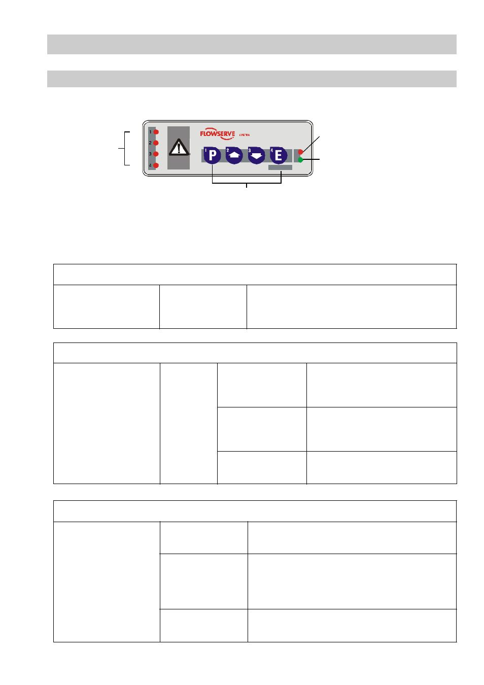
Assignment of signal LED / key / equipment:
LED 1 / Key 1: Limiter 1 (e. g. level electrode NRG 1x-40, low level LW)
LED 2 / Key 2: Limiter 2 (e. g. level electrode NRG 1x-40, low level LW)
LED 3 / Key 3: Limiter 3 (e. g. level electrode NRG 1x-41.1, high level HW)
LED 4 / Key 4: Limiter 4 (e. g. temperature transmitter TRV 5-40, MAX temperature)
Indication of system malfunctions in limiters 1 – 4
Limiters 1– 4,
one or more limiters
have a malfunction
LED 1, 2, 3, 4,
one or more LEDs
are flashing slowly
Output contacts open instantaneously.
Signalling output is operating in the switching
mode.
Analysis of system malfunctions in limiters 1 – 4
Limiters 1– 4,
one or more limiters
have a malfunction.
LED 1, 2, 3, 4,
one or more LEDs are
flashing slowly
Press and
hold down
corre-
sponding
key
(key 1, 2,
3 or 4)
LED 1 is flashing
slowly
Faulty communication between
limiter and controller,
HF interference
LED 2 and 3 are
flashing slowly
Excessively high temperature in the
terminal box of the electrode or the
temperature transmitter
LED 3 is flashing
slowly
Sensor defective.
Analysis of system malfunctions in the controller
LED bus status
is flashing slowly
Faulty communication within the CAN bus system.
HF interference
Malfunction
in control unit
LED bus status
is illuminated
Control unit defective.
Output contacts open instantaneously.
Signalling output is operating in the switching
mode.
LED Power is
flashing slowly
Bus supply voltage below 18 V.
GESTRA
NRS 1-40
GESTRA
NRS 1-40.1
TEST
Signal
LED
Malfunction alarm control unit
and bus status LED
Mains supply LED
Control keys
L1
L2
L3
L4
Fig. 8