Node id, Change node id, Node id change node id – Flowserve NRS1-40.1 User Manual
Page 31: Annex
31
– continued –
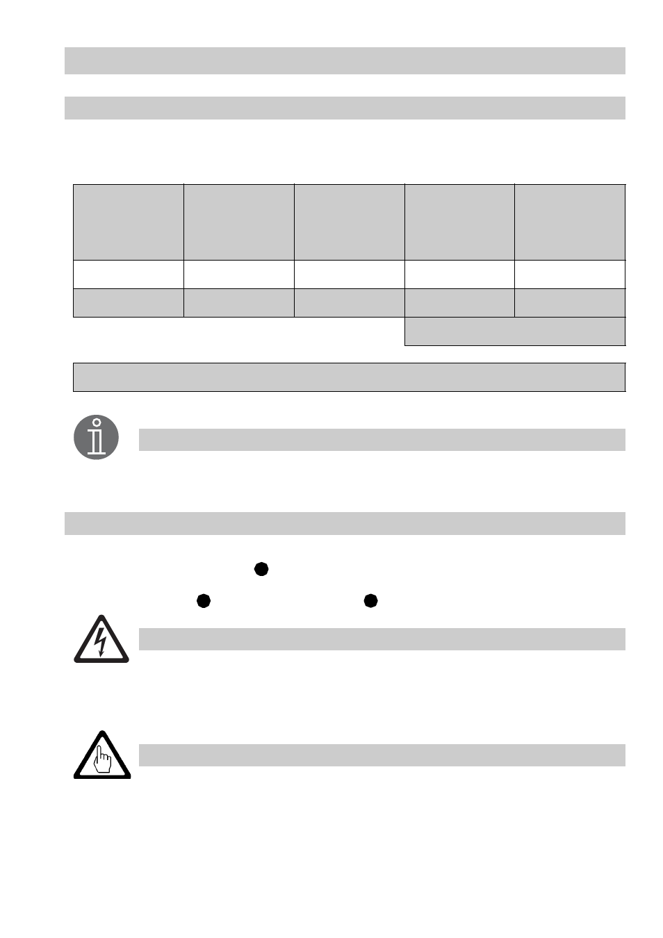
Node ID
Should it be necessary to establish other node IDs please take the interdependence of the equipment into
consideration and assign the node IDs for the individual group components according to the following
table:
The node ID 3* of the second level electrode NRG 1.-40 must be set on site since the equip-
ment features 2 as default factory setting.
Change node ID
With lower terminal strip unplugged:
Set the node ID via code switches
Fig.4 (S1 to S 7) a specified in the above table "Node ID" by using a
thin blade screwdriver.
Re-insert terminal strip
and fasten the fixing screws
. Enter the adjusted node ID on the name plate.
The terminal strips of the control unit NRS 1-40.1 are live during operation.
This presents the risk of severe cases of electric shock!
Always cut off power supply to the equipment before mounting, removing or connecting
the terminal strips!
A node ID must only be used for one piece of equipment in the CAN bus system.
The node ID 0 is not permissible.
Control unit
NRS 1-40.1
Sensor 1 e. g.
level electrode
NRG 1.-40
as device 1
Sensor 2 e. g.
level electrode
NRG 1.-40
as device 2
Sensor 3 e. g.
level electrode
NRG 1.-41.1
Sensor 4 e. g.
Temperature
transmitter
TRV 5-40
X
X +1
X +2
X +3
X +4
1
2
3*
4
5
Factory setting
Reserved area
Note
D
B
C
Dange r
Attention