Wiring diagram for can bus system - example, Wiring – Flowserve NRS1-40.1 User Manual
Page 15
15
– continued –
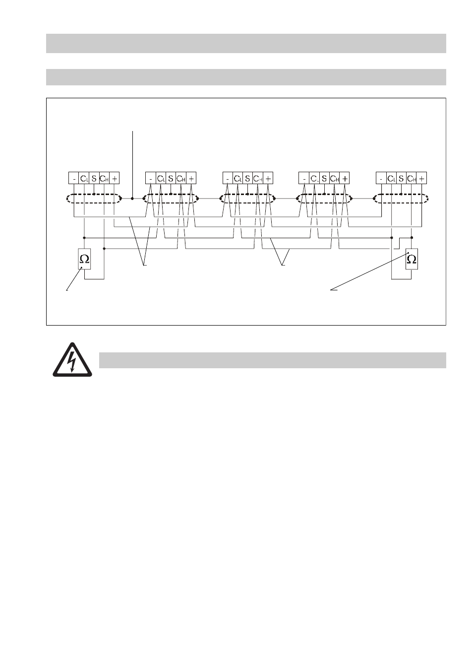
Wiring diagram for CAN bus system - ex ample -
■
Wire equipment in series. Star-type wiring is not permitted!
■
Link screens of bus cables such that electrical continuity is ensured and connect them
once to the central earthing point (CEP).
■
Because of the self-checking routine of the output contacts the control unit NRS 1-40.1
must always be the first equipment in the safety circuit, which means that terminal 25
must be permanently connected to L of the safety circuit.
■
Terminal N
1
(18) must be permanently connected to the zero potential (N) of the safety
circuit. Non-compliance will cause malfunctions, in particular if the control unit and the
safety circuit are supplied with different voltage potentials (e. g. control unit 230 V / safety
circuit 24 V). Provided that the electric potentials are equal, a wire link can be attached
to terminals 17 and 18.
■
To protect the switching contacts provide the circuit with a T 2.5 A or 1.0A fuse (TRD 604,
72 hrs. operation).
■
If two or more system components are connected in a CAN bus system, provide the first
and the last device with a terminating resistor of 120
Ω (terminal CL/CH).
■
Only one control unit NRS 1-40.1 may be used per CAN bus network.
■
The CAN bus system must not be interrupted during operation.
In the event of an interruption a malfunction alarm is raised.
Central
earthing point
CEP
Operating device
NRS 1-40.1
Level electrode
NRG 1x-40
Level electrode
NRG 1x-41.1
Temperature
transmitter
TRV 5-40
Terminating resistor
120
Ω
Terminating resistor
120
Ω
Voltage supply
CAN data line
Level electrode
NRG 1x-40
Fig. 6
Attention