4 rear panel configuration – Fluke Biomedical 4000M+ User Manual
Page 13
2
Operation
Rear Panel Configuration
2-5
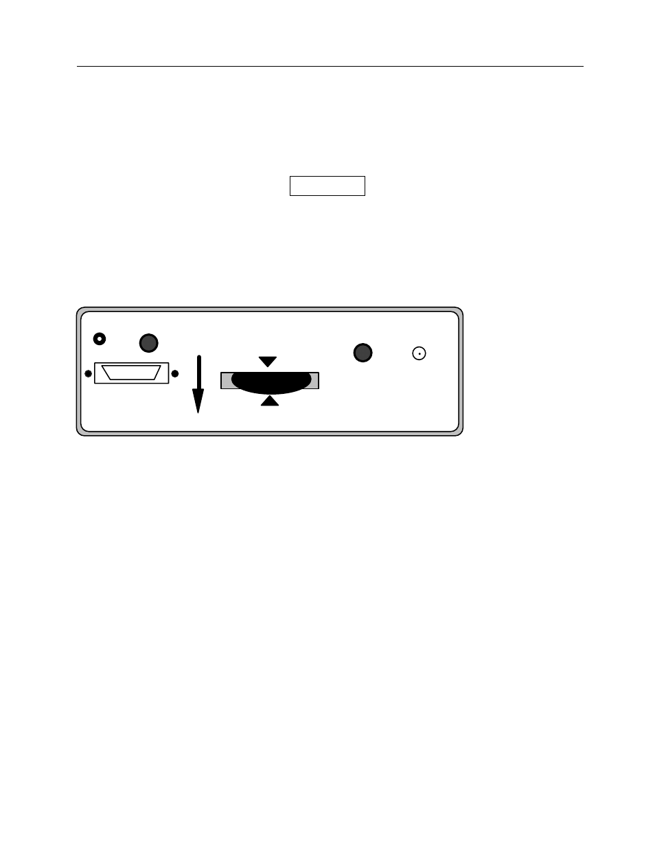
2.4 Rear Panel Configuration
Power Supply/Charge Connector
The Power Supply/Charge Connector for the AC Adapter is located on the rear panel and labeled
POWER (see Figure 2-2). An AC adapter is supplied with each unit. The AC adapter supplies 9 volts,
500 mA power to the unit and recharges the internal batteries.
CAUTION
Use only the AC Adapter Supplied with the unit;
other adapters may damage the unit.
Scope Connector
The Scope Connector is a BNC connector labeled SCOPE and located on the rear panel of the unit (see
Figure 2-2). This connector allows the detector waveform to be displayed on a storage oscilloscope. It
provides a voltage signal proportional to the radiation waveform as measured by the lightly filtered
detector.
BIAS
SIGNAL
BEAM
DIRECTION
kVp
RANGE
W/AI
SCOPE
POWER
RS-232
Figure 2-2.
Rear Panel Configuration
Filter Wheel
The filter wheel, located on the rear panel, allows selection of the kVp range. The wheel has six
positions:
• 27-42 (W/AI) or 21-50 (Mo/Mo)
• 35-60
• 50-85
• 70-120
• CHK
• 100-155
The numeric labels refer to the kVp range. The range associated with the position selected should
conform to the kVp setting of the X-ray machine. The CHK position is used for a calibration check.
Beam Direction Arrow
The Beam Direction Arrow shows how the unit must be positioned to accept x-rays from the x-ray
machine. For example, in the Fluoroscopic Mode, the unit must usually be turned upside down with the
black plastic disk facing the x-ray tube.