Fluke Biomedical ESA609 User Manual
Page 25
Electrical Safety Analyzer
Performing Electrical Safety Tests
13
Performing a Ground-Wire (Protective-Earth)
Resistance Test
The Ground-Wire (Protective-Earth) Resistance test
measures the impedance between the Analyzer’s test
receptacle’s PE terminal and the exposed conductive parts
of the DUT that are connected to the DUT’s Protective
Earth.
Prior to conducting any leakage tests with the Analyzer, it
is best to test the integrity of the ground connection
between the Analyzer’s test receptacle ground and the
DUT’s Protective earth ground or enclosure with this test.
To perform a ground-wire resistance test:
1. Press
to show the resistance function menu.
2. Connect one end of a test lead to the
Ω
/A jack as
shown in Figure 4.
•
If using an accessories probe, connect it to the
other end of the test lead and place the probe tip
into the Ground Pin of the Analyzer’s test
receptacle (black input jack).
•
If using an alligator clip accessory, connect it to
the other end of the test lead, place the null post
adapter in the Ground Pin of the Analyzer’s test
receptacle (black input jack), and clamp the
alligator clip to the null post adapter.
3. Press the softkey labeled Zero. The Analyzer zeroes
out the measurement to cancel the test lead
resistance.
4. Connect the test lead coming from the red jack to the
DUT enclosure or protective earth connection.
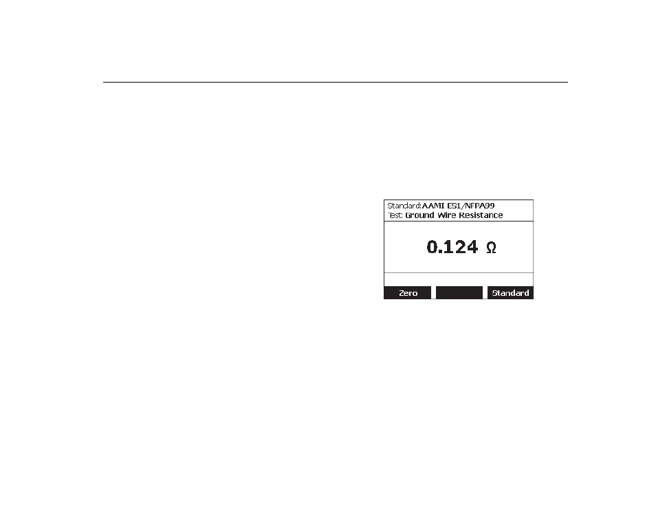
5. Plug the power cord from the DUT into the Analyzer’s
test receptacle. The measured resistance displays as
shown in Figure 7 after any the DUT connections are
made.
fis205.bmp
Figure 7. Ground-Wire Resistance Test
Warning
To avoid electric shock, remove the null post
adapter from the test receptacle after a test
lead zero is performed. The test receptacle
becomes potentially hazardous during some of
the test conditions.