Performing an insulation resistance test – Fluke Biomedical ESA620 User Manual
Page 37
Electrical Safety Analyzer
Performing Electrical Safety Tests
23
Performing an Insulation Resistance Test
The five insulation resistance tests take measurements
on mains (L1 & L2) to Protective earth, applied parts to
Protective earth, mains to applied parts, mains to non-
earthed accessible conductive points, and applied parts
to non-earthed accessible conductive points.
To access the Insulation Resistance Test menu,
press .
All Insulation Resistance Tests can be performed using
500 or 250 volts dc. To change the test voltage from the
Insulation Resistance Test menu, press the softkey
labeled More. Pressing the softkey labeled Change
Voltage will cause the test voltage to toggle between 250
and 500 volts dc.
Note
Exiting and re-entering the Insulation Resistance
Test menu causes the test voltage to return to its
default value of 500 volts dc.
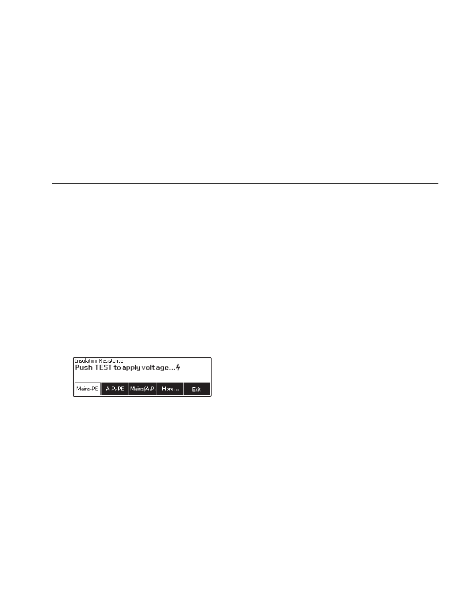
faw15.eps
Figure 12. Insulation Resistance Measurement
As shown in Figure 12, three of the five tests are shown
over function soft keys F1 through F3. To access the
other two tests or test voltage selection, press the softkey
labeled More. The softkey labeled Back will move the
menu back up to the top-level insulation resistance test
menu.
After selecting one of the tests by pressing the
appropriate softkey, press to apply the selected
voltage to the DUT and take the resistance measurement.
Figure 13 through 17 shows the electrical connections
between the Analyzer and DUT for the five insulation
resistance tests.
Note
The DUT is powered off for this test.