Specifications installation and operation – FSR CI-5 BWPA User Manual
Page 2
VIDEO INPUT
Number/type:
1 VGA / SVGA / XGA / SXGA / UXGA / RGBHV / RGBS / RGsB / RsGsBs
Connectors:
One 15 pin HD female
Level (nominal):
Analog 0.7v p-p
Level (maximum):
2v p-p
Impedance:
75 ohms
VIDEO OUTPUT
Number/type:
1 VGA / SVGA / XGA / SXGA / UXGA /
RGBHV / RGBS / RsGsBs
Connectors:
4” Pig-tail of 5 female BNC’s ( RGBHV )
Bandwidth:
700MHz @ -3.0dB (5 BNC output)
400MHz @ -3.0dB (HD-15 loopback output)
Level (nominal):
Unity / User adjustable via DIP switch settings
Gain:
OFF = 0’ to 75’
LOW = 75’ to 125’
MEDIUM = 125’ TO 175
HI = 175’ to +200’
Impedance:
75 ohms
AUDIO
CI-5BWPA/CI-5LB
PCI-5BWPA
Bandwidth:
20 Hz to 20 kHz (+/-0.05dB)
100 Hz to 15kHz (+/-2dB)
THD + Noise:
0.01% @ 20 kHz at rated Max Output S/N >98dB
0.5% between 275 Hz-3.5kHz
Noise Floor:
Better than 98dB
NA
Stereo separation:
-90dB @ 1 kHz
-40dB @ 1kHz
Audio Gain
+6dB
0dB with 1.5dBm max insertion loss
AUDIO INPUT
Number/type:
1 stereo unbalanced
1 stereo unbalanced
Connectors:
1/8” mini connector
1/8” mini connector
Impedance:
10K ohms DC coupled unbalanced
600 ohms
Max level:
+6dBm
+20dBm
AUDIO OUTPUT
Number/type:
1 Balanced / Unbalanced Stereo
1 Balanced / Unbalanced Stereo
Connector:
5 Position Captive screw terminal
2, 3 position captive screw terminals
Impedance:
50 ohm
Maximum Level:
600 ohms: +12dBm Balanced / +6dBm Unbalanced
600 ohms
Hi – Z: +14dBm Balanced / +8dBm Unbalanced
+20dBm
SYNC
Input level:
2.0v to 5.0v p-p
Output level:
TTL to 5.0v p-p
Input Impedance:
475 ohms
Output impedance:
75 ohms
Polarity:
Positive or negative
Horizontal frequency:
15kHz - 200kHz
Vertical frequency:
30 Hz - 150 Hz
GENERAL
Power:
9v AC / DC, 50/60 Hz: 8 – 14v DC, 9v AC Power Supply
included. May be remotely located up to 150 feet away from
the wallplate when using 22 Gage / 2 Conductor cable.
Mounting:
Single – Gang Decora Wallplate ( Included )
Colors:
Black, White, Ivory
Enclosure Type:
Metal
Size:
4.094” H x 1.706” W x 0.65” D
Approvals:
UL / CE
SPECIFICATIONS
INSTALLATION AND OPERATION
The 5 BNC output cable, 9 VAC power supply leads and audio leads should be prewired
through the duplex back box prior to completing the steps below. Do not plug in the power
supply until all wiring is completed and proper connections are verifi ed.
Connect the 5 BNC female “pigtail” connectors to the 5 BNC male output cable leading to
the projector or monitor.
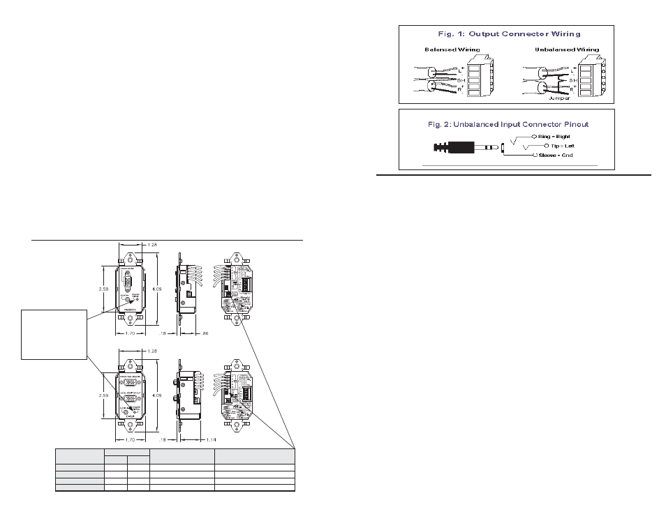
Connect the audio output cables to the captive screw terminals labeled “Audio Out”. The
appropriate wiring confi guration for balanced and unbalanced connections is shown in
Figure 1 to the right of this page.
Using the chart on the rear of the wallplate or below as a guide, set the cable equalization
dip switches for optimum performance at the desired cable length.
Connect the 9 VAC power supply output leads to the captive screw terminals labeled “9V”
and “AC”. Attach the video input from the desired source. Plug in the power supply. On
the units face, an amber LED will indicate power. The LED should change to green when a
proper video signal is present on the HD-15 input (horizontal sync is present).
After confi rming proper operation, unplug the power supply, and mount the CI–5 and cover
plate in the wall. Be certain that all cables and connectors are nested properly and check
for pinched or strained cables while mounting the CI - 5 interface into the wall box. Use the
supplied screws for mounting. Install the cover plate with the supplied screws and perform
the fi nal operational check.
AMBER LED INDICATES
POWER IS PRESENT
GREEN LED INDICATES
HORIZONTAL SYNC IS
PRESENT ON THE VIDEO
INPUT
DIP SWITCH
SETTINGS
POSITION
OPTIMAL CABLE
LENGTH (FT)
ACCEPTABLE CABLE
RANGE (FT)
S2
S1
OFF
0
0
50
0-75
LOW
0
1
100
75-125
MED
1
0
150
125-175
HIGH
1
1
200
175-200
200
200