Installation and operation, Utp pwr out re d = ov erlo a d, 24vdc, 2.7a max – FSR TwisterPro User Manual
Page 3: Utp pwr out re d = o v e rl oad
5
T-PRO SERIAL
ADAPTER
REAR PANEL CONNECTION
POWER INPUT
INPUT
STEREO AUDIO INPUT
OUTPUT
STEREO AUDIO
OUTPUT
IR OUTPUT
UTP Input
to TPRO
Receiver
UTP
PWR
OUT
Re
d
=
Ov
erlo
a
d
Local Monitor Out
Computer Video In
Power 24VDC
.09A+TPRO-RX
Audio In
L Gnd R
IR
In Gnd In
RS232
OUTPUT
STEREO AUDIO
IR OUTPUT
OUTPUT
STEREO AUDIO
IR OUTPUT
OUTPUT
STEREO AUDIO
IR OUTPUT
OUTPUT DEVICE
EXTERNAL IR
(BY CUSTOMER)
INPUT FOR
RS-232
OUTPUT
RS-232
OUTPUT
RS-232
OUTPUT
RS-232
RS-232
REAR PANEL
POWER
24VDC, 2.7A MAX.
UTP Input
from TPRO
Transmitter
UTP
PWR
OUT
Re
d
=
Ov
erlo
a
d
Serial Out
Computer Video Out
Power 24VDC
.19A+TPRO-TX
Out
L Gnd R
Audio
Out
IR
UTP Input
from TPRO
Transmitter
UTP
PWR
OUT
Re
d
=
O
v
e
rl
oad
Serial Out
Computer Video Out
Power 24VDC
.19A+TPRO-TX
Out
L Gnd R
Audio
Out
IR
UTP Input
from TPRO
Transmitter
UTP
PWR
OUT
Re
d
=
O
v
e
rl
oad
Serial Out
Computer Video Out
Power 24VDC
.19A+TPRO-TX
Out
L Gnd R
Audio
Out
IR
MONITOR
RECEIVER
MONITOR
RECEIVER
MONITOR
RECEIVER
MONITOR
RECEIVER
TPRO-HUB
TPRO-HUB
PC
(POWERS ALL DEVICES)
HUB POWER SUPPLY
(POWERS ALL DEVICES)
HUB POWER SUPPLY
TRANSMITTER
NO MORE THAN 3 HUBS DEEP
INPUT FOR
OPTIONAL - FSR P/N
(REAR PANEL)
PS-24DC-500MA
OPTIONAL - FSR P/N
POWER INPUT (REAR PANEL)
PS-24DC-500MA
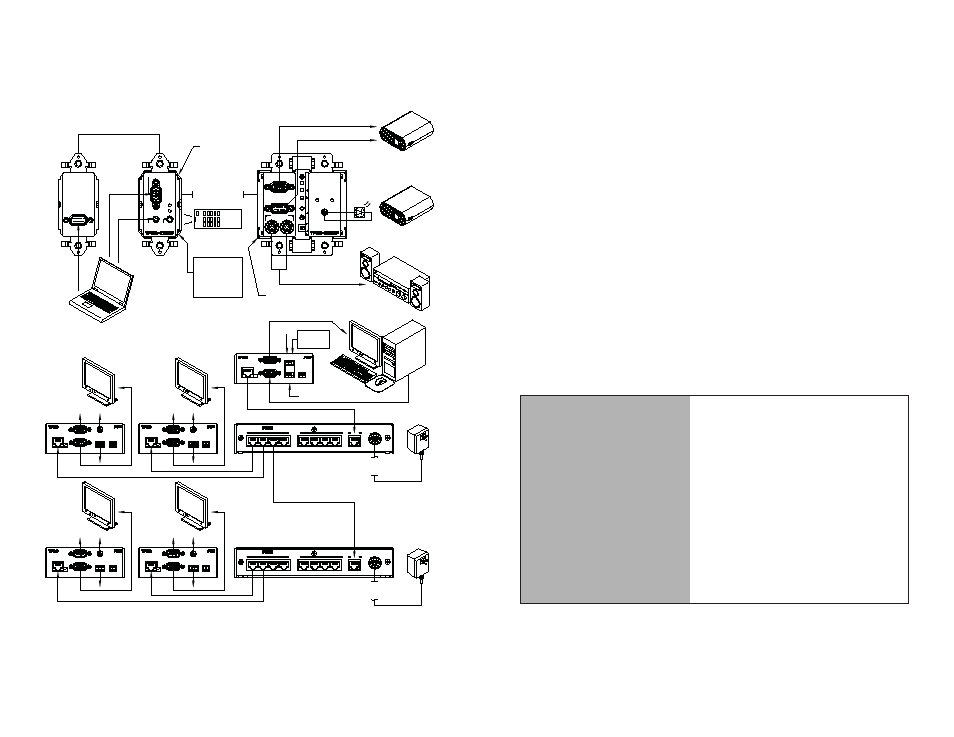
Typical application with TPRO single Transmitter and Receiver
Typical application using multiple TPRO-HUB's
VIDEO
RS-232
(SEE SPECS FOR
CABLE LENGTHS)
PROJECTOR
PROJECTOR
STEREO AUDIO OUTPUT
IR-EC2-6
OPTIONAL
EMITTER
TPRO-TXWP
TPRO-RXWP
CAT5 CABLE
UTP Input
from TPRO
Transmitter
UTP
PWR
OUT
Re
d
=
Ov
erlo
a
d
Serial Out
Computer Video Out
Power 24VDC
.19A+TPRO-TX
Out
L Gnd R
Audio
Out
IR
Woodland Park,
NJ 07424
244 Bergen Blvd.
Model
TPRO-HUB
1
2
4
3
5
6
7
8
OUTPUT
INPUT
POWER
24VDC, 2.7A MAX.
Woodland Park,
NJ 07424
244 Bergen Blvd.
Model
TPRO-HUB
1
2
4
3
5
6
7
8
OUTPUT
INPUT
COMPUTER VIDEO IN
POWER/
VIDEO
DATA
AUDIO IN
IR SENSOR
COMPUTER
VIDEO OUT
SERIAL OUT
L
R
AUDIO OUT
POWER/
VIDEO
DATA
IR OUT
S
E
L
E
C
T
G
A
I
N
B
O
O
S
T
O
N
V
IR
VIDEO
AUDIO
PC/LAPTOP
CONTROL
IR REMOTE
OR
RS-232
OUTPUT DEVICE
EXTERNAL IR
(BY CUSTOMER)
OPTIONAL
6
Installation and Operation
Mount the units as appropriate for the particular installation.
TPRO Brick style models:
There are #6-32` tapped holes on the top and bottom of the TPRO for
mounting. Use #6-32 screws that protrude through no longer than 1/2".
There are also rack kits available from FSR for mounting in a standard
19” rack mount. See “accessories” section for FSR part numbers and
ordering information.
TPRO Wallplate style models:
The TPRO resembles a decora style duplex outlet shape and will mount
into a standard gang box. Connect the RJ-45 jack and power supply
leads BEFORE mounting the unit in the gang box. Always check for
cable clearance while mounting.
The input power connector is polarity sensitive and depending on the
installation, should be connected to the transmitter, receiver or hub. Do
not plug in the supplies until all cables are tested.
Cabling Installation details:
RECOMMENDED
TRANSMISSION RANGE
0-1000 ft with a single power supply (Up
to 600’ when powered at transmitter. Up
to 1000’ when powered at receiver)
When using a TPRO-HUB with included
power supply:
The maximum distance to a
transmitter is 1000’
The maximum distance to a receiver
is 600’ *
* A distance of up to 1000’ can be
achieved by adding an additional power
supply at the receiver
Install and terminate the UTP cable, taking note of the following:
The cable must be terminated using the EIA/TIA-568B standard pairing.