GAI-Tronics 234L(x)-xxx LITE Series Stanchions User Manual
Page 12
Pub. 42004-393B
Model 234L(x)-xxx LITE Series Stanchion
Page: 11 of 18
\\s_eng\gtcproddocs\standard ioms - current release\42004 instr. manuals\42004-393b.doc
03/07
3. Connect the proper power source to the stanchion. For ac powered stanchions, power should be
routed to the ac weatherproof box located at the bottom of the stanchion. For 12 V dc powered
stanchions, the corresponding 12 V dc can be routed directly into the weatherproof box containing the
relay and terminal block. Attach the power input directly to the terminal block (positive = red or
white, negative = black). All cable entering or exiting the weatherproof boxes must be properly
sealed with the supplied Heyco bushings or properly sized conduit fittings. For 12 V dc stanchion
models, skip to step 6.
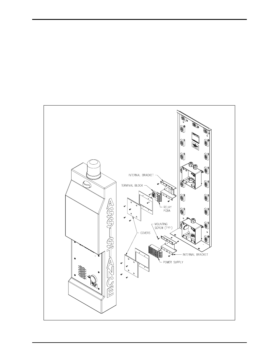
4. To attach the incoming ac power to the power switcher, remove the two screws holding the internal
mounting bracket. The switching power supply is attached to this bracket. Connect incoming ac
power to the corresponding connection point on the power switcher (H = black, N = white, ground
symbol = green). Refer to Figure 7.
Figure 7. Power Supply - Exploded View