GAI-Tronics 293-700 VoIP Telephone User Manual
Page 14
P
UB
.
42004-397G
V
O
IP
T
ELEPHONES
P
AGE
12 of 23
f:\standard ioms - current release\42004 instr. manuals\42004-397g.doc
11/09
Power
Power-Over-Ethernet (POE)
Connect power to the system as indicated in your POE equipment manual.
Local Power
When POE is not available, this telephone can operate from a local 48 V dc power source. A removable
terminal block P11 has been provided for connection of local power to the telephone. Connect the
positive conductor to the (+) terminal and the negative conductor to the (-) terminal of P11.
Ground
The enclosure of each phone must be connected to earth ground. Install a #6 ring lug on the ground
conductor prior to connection to the ground screw located on the rear of the front panel.
Network Cable
Connect a Cat5 or Cat5e UTP cable with an RJ45 connector between the Local Area Network (LAN) and
the VoIP PCBA.
I/O
Inputs
Four auxiliary inputs have been provided for customer use. Terminations for these inputs are provided on
terminal block TB1. Connect each input between the desired input (INPUT 1-4) and common (COM) on
terminal block TB1. Please refer to the Inputs section of Pub. 42004-396 for programming instructions
for these inputs.
Outputs
Two outputs have been provided for customer use. Terminations for these outputs are provided on
connector P1. Output 1 is a single pole, N.O. contact. Output 2 is a single pole with both a N.O. and
N.C. contact. Please refer to the Outputs section of Pub. 42004-396 for programming instructions for
these outputs.
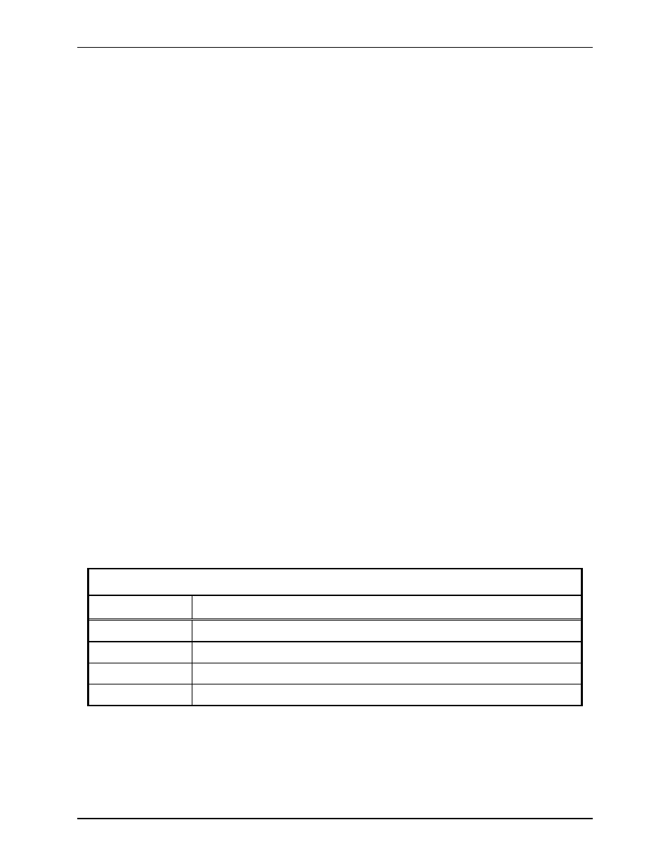
Recommended Cabling
Table 1. Recommended Cabling
Cable Use
Size
LAN
Cat5 or Cat5e UTP cable with an RJ45 connector
Power
2-conductor, No. 22 AWG is typical
Inputs
2-conductor, No. 22 AWG is typical
Output contacts
2 or 3-conductor, No. 18 AWG is typical
- 293AL-700 VoIP Telephone 297-700 VoIP Telephone 297-702 VoIP Telephone 298-701 VoIP Telephone 294AL-702 VoIP Telephone 297-701 VoIP Telephone 297-703 VoIP Telephone 298-702 VoIP Telephone XTA0003A Radio Cable 12564-002 Party Line Knob Kit (EuroPage) 12598-004 Redundant 48 V DC Module XGM003A Gooseneck Microphone Kit 12515-007, 12515-008, 12515-009 Pressbar Handset with Hytrel Cord Replacement Kit 10959-207 and 10959-208 Rack-mount Audio Messenger Interface 10959-201 and 10959-203 Wall-mount Audio Messenger Interface 10959-903 Wall-Mount Audio Messenger Interface (AMI) 12598-002 Redundant 5 V DC Module 13340 Constant Directivity Horn 231-001 Pole Mounting Kit 227-003 Auto-dial S.M.A.R.T. Phones 247-003 Auto-dial S.M.A.R.T. Phones 257-003 Auto-dial S.M.A.R.T. Phones 277-003 Auto-dial S.M.A.R.T. Phones 226-003 S.M.A.R.T. Phones with Keypads 256-003 S.M.A.R.T. Phones with Keypads 246-003 S.M.A.R.T. Phones with Keypads 276-003 S.M.A.R.T. Phones with Keypads XTI0001A-G3 Radio Cable