GAI-Tronics 293-700 VoIP Telephone User Manual
Page 8
P
UB
.
42004-397G
V
O
IP
T
ELEPHONES
P
AGE
6 of 23
f:\standard ioms - current release\42004 instr. manuals\42004-397g.doc
11/09
Models 293-700, 293AL-700, and 294AL-702
The mounting and wiring instructions for Models 293-700, 293AL-700 and 294AL-702 are as follows:
1. Remove the four tamper-resistant screws from
the front panel.
2. Position the enclosure on the mounting
surface. The enclosure provides four
0.28-inch mounting holes. Secure it with the
four ¼-inch diameter bolts of the appropriate
length for the mounting surface.
N
OTE
: When using the GAI-Tronics Model
231-001 Pole Mounting Kit, follow the
mounting instructions provided in the kit.
3. For Model 293-700 only: Create an access
hole using a Greenlee-type punch that is
equivalent in size to the conduit diameter.
Bottom entry is strongly recommended. Insert
a conduit fitting in the access hole. Refer to
conduit installation details on page 5.
N
OTE
: Use silicone sealant or equivalent
around and inside all conduit entries.
4. Pull the cable through the conduit. Install the cable as shown in the Field Wire Installation section on
page 11.
5. Make hardware configuration changes, if necessary. Refer to page 14 for more information.
6. Perform the initial programming of the phone. Refer to the Programming section on page 16. Verify
that the phone is operating properly by calling to and from another phone.
7. Adjust the speaker levels if necessary. Refer to the Speaker Level section on page 15.
8. Complete the installation by attaching the front panel assembly to the rear enclosure using the four
tamper-resistant screws.
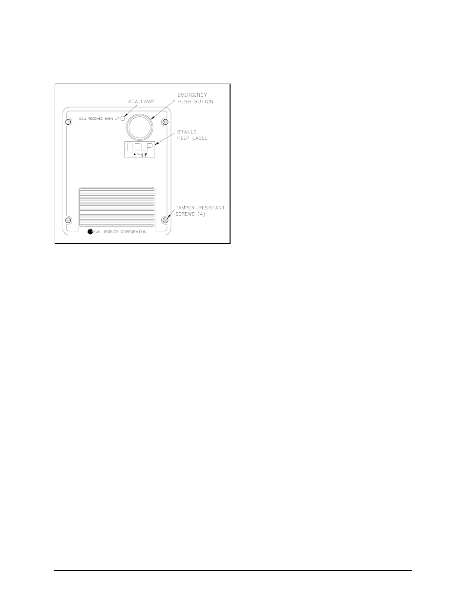
Figure 5. Model 293-700 VoIP Phone in a Non-
metallic Enclosure
- 293AL-700 VoIP Telephone 297-700 VoIP Telephone 297-702 VoIP Telephone 298-701 VoIP Telephone 294AL-702 VoIP Telephone 297-701 VoIP Telephone 297-703 VoIP Telephone 298-702 VoIP Telephone XTA0003A Radio Cable 12564-002 Party Line Knob Kit (EuroPage) 12598-004 Redundant 48 V DC Module XGM003A Gooseneck Microphone Kit 12515-007, 12515-008, 12515-009 Pressbar Handset with Hytrel Cord Replacement Kit 10959-207 and 10959-208 Rack-mount Audio Messenger Interface 10959-201 and 10959-203 Wall-mount Audio Messenger Interface 10959-903 Wall-Mount Audio Messenger Interface (AMI) 12598-002 Redundant 5 V DC Module 13340 Constant Directivity Horn 231-001 Pole Mounting Kit 227-003 Auto-dial S.M.A.R.T. Phones 247-003 Auto-dial S.M.A.R.T. Phones 257-003 Auto-dial S.M.A.R.T. Phones 277-003 Auto-dial S.M.A.R.T. Phones 226-003 S.M.A.R.T. Phones with Keypads 256-003 S.M.A.R.T. Phones with Keypads 246-003 S.M.A.R.T. Phones with Keypads 276-003 S.M.A.R.T. Phones with Keypads XTI0001A-G3 Radio Cable