Connecting a beacon – GAI-Tronics 293-700 VoIP Telephone User Manual
Page 15
P
UB
.
42004-397G
V
O
IP
T
ELEPHONES
P
AGE
13 of 23
f:\standard ioms - current release\42004 instr. manuals\42004-397g.doc
11/09
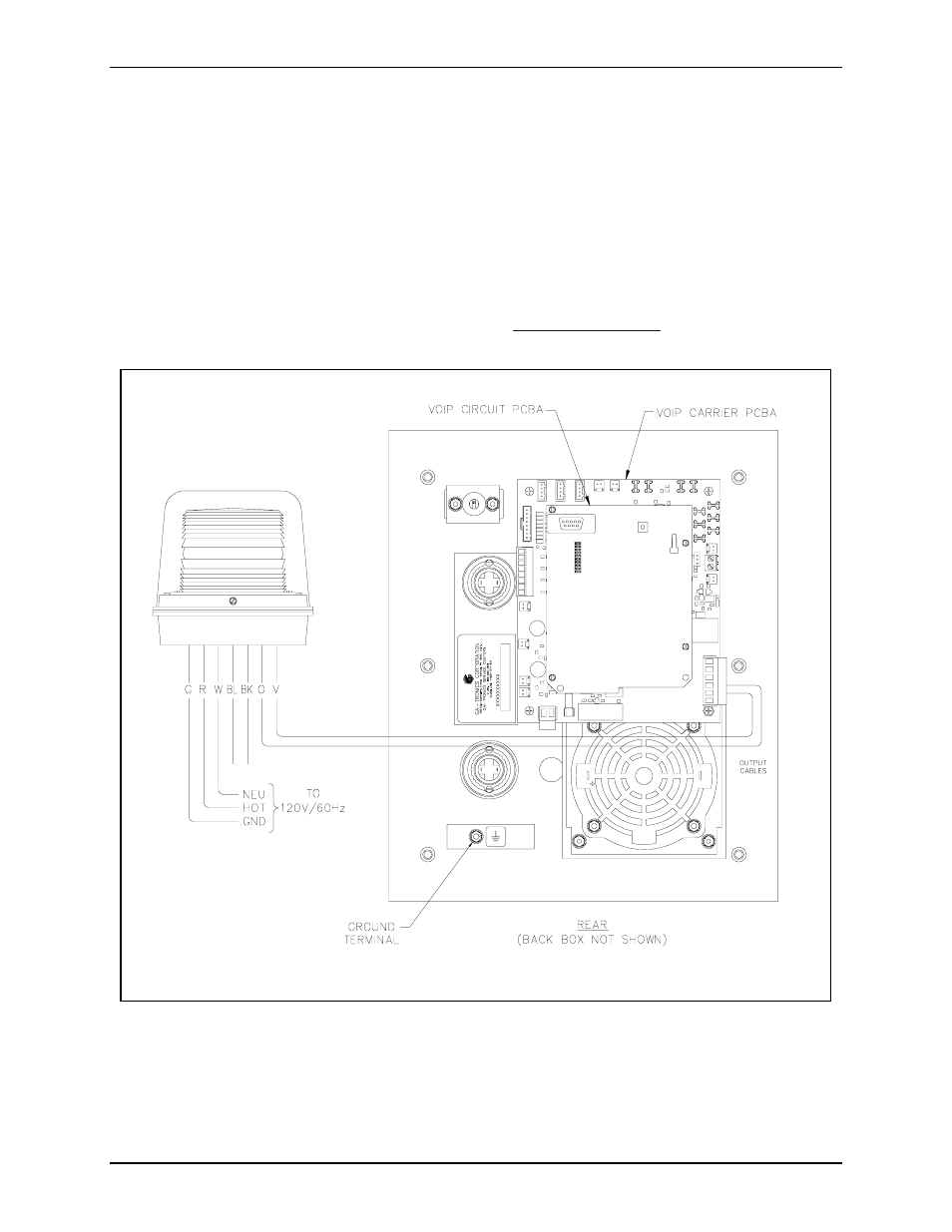
Connecting a Beacon
Each phone includes two solid state relays. Contact 1 on P1 of the VoIP Carrier PCBA provides the
connections for a beacon output. Refer to Figure 17 for the connection details.
Contact 1 allows peripheral equipment, such as beacons, video cameras, and alarm generators, to be
activated when the E
MERGENCY
push button is pressed. The relay remains energized for the duration of
the emergency call.
In many applications, the output is used to operate a GAI-Tronics Model 530-001/531A Beacon (sold
separately). For connection details, please refer to the Model 530-001/531A installation instructions
included with the beacon. Information is also available at
www.gai-tronics.com
.
Figure 17. Model 297-700 and 298-701 - Component Locations
(shown with connection to optional GAI-Tronics 530-001/531A Beacon)
- 293AL-700 VoIP Telephone 297-700 VoIP Telephone 297-702 VoIP Telephone 298-701 VoIP Telephone 294AL-702 VoIP Telephone 297-701 VoIP Telephone 297-703 VoIP Telephone 298-702 VoIP Telephone XTA0003A Radio Cable 12564-002 Party Line Knob Kit (EuroPage) 12598-004 Redundant 48 V DC Module XGM003A Gooseneck Microphone Kit 12515-007, 12515-008, 12515-009 Pressbar Handset with Hytrel Cord Replacement Kit 10959-207 and 10959-208 Rack-mount Audio Messenger Interface 10959-201 and 10959-203 Wall-mount Audio Messenger Interface 10959-903 Wall-Mount Audio Messenger Interface (AMI) 12598-002 Redundant 5 V DC Module 13340 Constant Directivity Horn 231-001 Pole Mounting Kit 227-003 Auto-dial S.M.A.R.T. Phones 247-003 Auto-dial S.M.A.R.T. Phones 257-003 Auto-dial S.M.A.R.T. Phones 277-003 Auto-dial S.M.A.R.T. Phones 226-003 S.M.A.R.T. Phones with Keypads 256-003 S.M.A.R.T. Phones with Keypads 246-003 S.M.A.R.T. Phones with Keypads 276-003 S.M.A.R.T. Phones with Keypads XTI0001A-G3 Radio Cable