Data, Port 1 & port 2, Mode switch – GAI-Tronics 10959-209 Audio Messenger Interface for ADVANCE User Manual
Page 7: Status
Pub. 42004-492A
M
ODEL
10959-209
A
UDIO
M
ESSENGER
I
NTERFACE FOR
ADVANCE
P
AGE
5 of 16
f:\standard ioms - current release\42004 instr. manuals\42004-492a.docx
08/14
Data
The DB-9 connector labeled DATA, located on the rear of the AMI, interfaces to the Master Control Unit
(MCU) serving the ADVANCE control system. Depending on the position of the MODE Switch, the
AMI will respond to one of two communication pathways, i.e. COM1 or COM 2 (RS-485) indigenous to
the MCU.
Port 1 & Port 2
The RJ-45 connectors, labeled PORT 1 and PORT 2, interconnect to the External Audio Interface (EAI)
PCBA associated with the ADVANCE system, and allow multiple audio paths (page, party line 1 and
party line 2) to be interfaced to a SmartSeries system. In addition to audio paths, the ports also serve as a
pathway for input and output control contacts to facilitate play, off-hook, and system failure notification.
Mode Switch
The slide-switch labeled MODE, determines which communication pathway from the MCU the AMI will
use. In position 1 the AMI utilizes COM 1 pathway, whereas in position 2 it uses COM 2. The system
configuration requires that one of the two required AMI be set to MODE “1” and that the second AMI be
set to MODE “2”, thus allowing a sharing of MCU resources.
Status
The 3-position terminal labeled STATUS allows external notification of an AMI failure and/or assurance
of healthy and nominal operation via a fault relay (single Form C, contact maximum current = 1A).
Nominal operation is indicated by an open circuit between the FLT and COM contacts; a fault condition
is indicated by a closed circuit between FLT and COM.
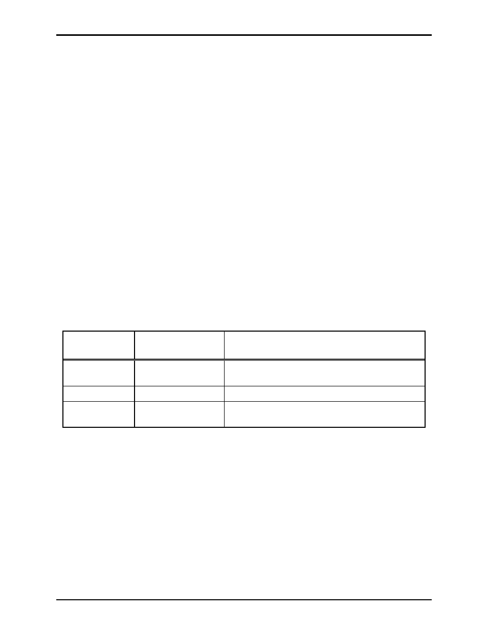
Table 1. Power Assignment
Metalwork
Label
Internal Terminal
Pin-Out
Function or ACT Description
HEALTHY
TB1-1
Indicate nominal operation with short-circuit between
TB1-1 and TB1-2
COM
TB1-2 Relay
Common
FAULT
TB1-3
Indicate fault condition with short-circuit between
TB1-3 and TB1-2