GAI-Tronics 10962-001, 10962-002 AMI Redundant Controller Modules User Manual
Page 11
Pub. 42004-708L2B
Model 10962-001 and 10962-002 AMI Redundant Controller Modules
Page: 11 of 17
f:\standard ioms - current release\42004 instr. manuals\42004-708l2b.doc
06/10
RS-232 Receptacle
The RS-232 connector is for a serial data connection to the AMI. This data line allows the ARC to
monitor the operating status of the AMI and also to control playing of the AMI messages. The RS-232
data line is DISABLED as the factory default. Prior to using this connection, it must be enabled using the
ARC’s embedded web page configuration screen. An RJ11 type modular cable is connected between this
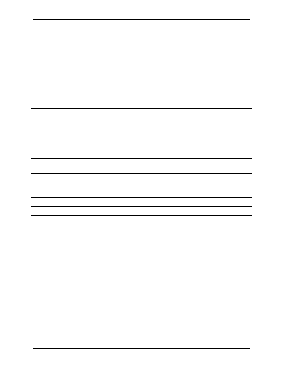
connector and the accessory jack on the AMI front panel. Cable pin-out is as follows:
N
OTE
1: When using the RS-485 data connection, the RS-232 cannot be used and vise versa.
N
OTE
2: If the ARC and the AMI are not powered from the same source, a GND connection must be
made between them for the RS-232 communication to work properly. Connect the GND connection on
the Logic Inputs terminal block on the ARC to the GND connection on the Digital Inputs terminal block
on the AMI.
ARC
Pin No.
Function
AMI
Pin No.
Notes:
1 Spare
1
2
Data TX (to AMI)
7
3
PTT
6
Used only when paging microphone is required for
AMI.
4
Mic HI
4
Used only when paging microphone is required for
AMI.
5
Mic Lo
5
Used only when paging microphone is required for
AMI.
6 Spare
7
Data RX (from AMI)
2
8 Spare
ADDR Hex Switch
The hex switch labeled ADDR is used to set the operating mode of the ARC on initial power-up. Each
time the ADDR switch is changed, the unit must be restarted for the new setting to be recognized. Reset
the ARC by momentarily removing power.
When the ADDR switch is set to “0” the ARC is the “primary” controller meaning that in normal
operation, the AMI connected to it will be the “ACTIVE” alarm generator.
When the ADDR switch is set to “1” the ARC is the “secondary” controller meaning that in normal
operation, the AMI connected to it will be the “BACK-UP” alarm generator.
All other ADDR settings (2–F) are invalid for normal operating mode and should not be selected.