Installation, Mounting, Wiring terminations – GAI-Tronics 10962-001, 10962-002 AMI Redundant Controller Modules User Manual
Page 5: Figure 5. redundant controllers - rear panels
Pub. 42004-708L2B
Model 10962-001 and 10962-002 AMI Redundant Controller Modules
Page: 5 of 17
f:\standard ioms - current release\42004 instr. manuals\42004-708l2b.doc
06/10
Installation
Mounting
The Model 10962-001 and -002 Redundant Controller Modules can be mounted in a standard EIA 19-
inch electronic equipment rack. Each model requires 1U (1.75 inches) of rack space. Complete the
following steps for mounting in the rack:
1. Attach the mounting brackets with the eight 8-32
× 3/8-inch screws provided.
2. Mount the AMI Redundant Controller into the rack using four 10-32
× ¾-inch screws with plastic
shoulder washers.
Wiring Terminations
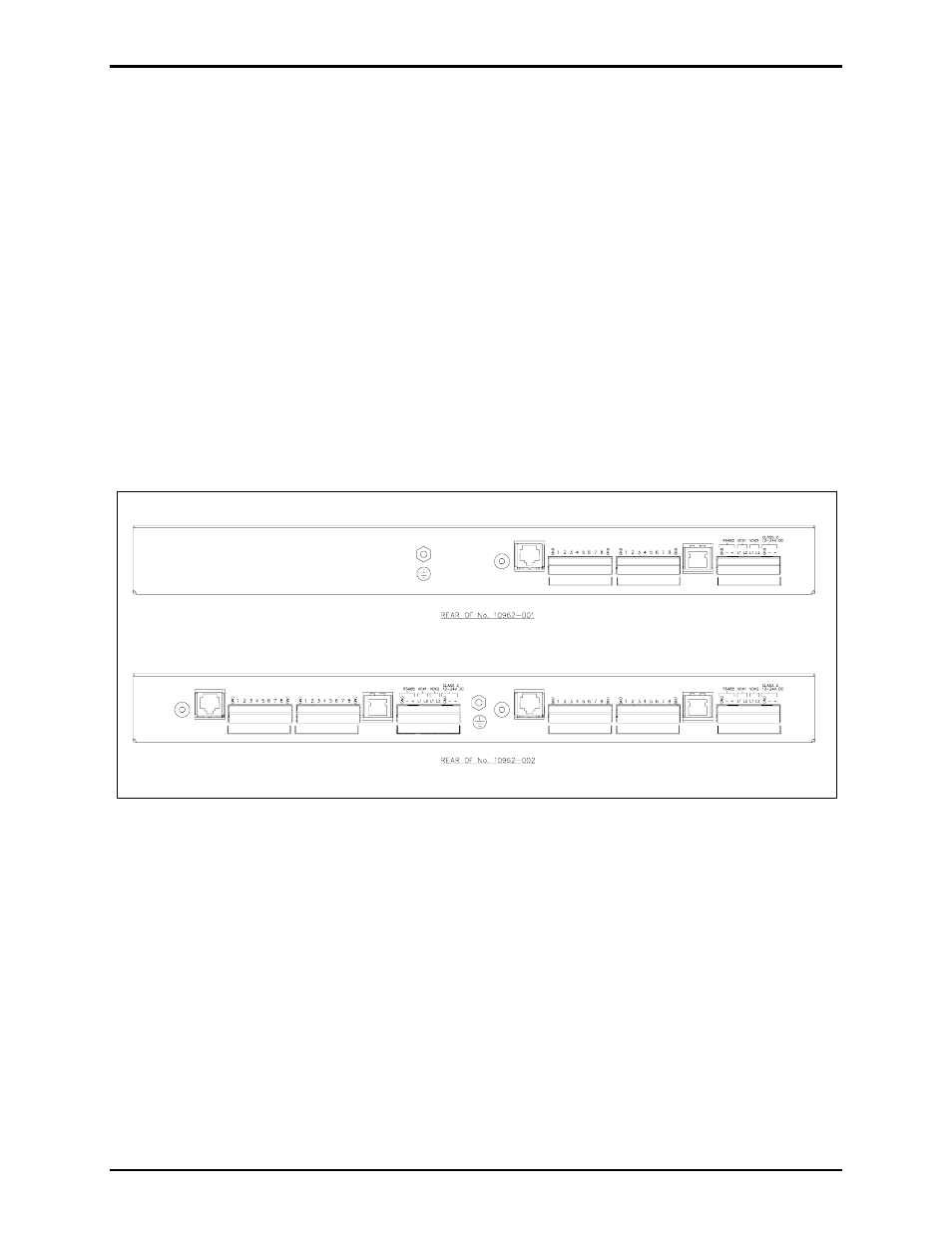
The Model 10962-001 AMI Redundant Controller provides three terminal blocks, an RJ11 receptacle
labeled RS-232,
and an RJ45 receptacle labeled ETHERNET on the rear panel for wiring connections.
The Model 10962-002 is equipped with two sets of terminal blocks and receptacles since it has two
PCBAs. Refer to Figure 5 below for terminal locations.
ETHERNET
SYSTEM
LOGIC INPUTS
LOGIC OUTPUTS
RS232
ADDR
SYSTEM
ETHERNET
RS232
LOGIC INPUTS
ADDR
LOGIC OUTPUTS
LOGIC OUTPUTS
LOGIC INPUTS
SYSTEM
ETHERNET
RS232
ADDR
Figure 5. Redundant Controllers - Rear Panels