Ics smartseries ac-powered plug-in amplifiers, 901ics, 701-902ics & 701-904ics, Opening and closing the amplifier – GAI-Tronics 701-302ICS ICS AC-Powered Page/Party Plug-in Amplifiers User Manual
Page 12
Pub. 42004-730L2B
ICS AC-Powered Page/Party
®
Plug-in Amplifiers
Page: 10 of 20
f:\standard ioms - current release\42004 instr. manuals\42004-730l2b.doc
04/11
ICS SmartSeries AC-Powered Plug-in Amplifiers
Models 751-901ICS, 701-902ICS & 701-904ICS
The SmartSeries PCBA adds microprocessor control to the Page/Party
®
station, providing additional
sensor and monitoring capabilities, such as Ambient Level Sensing (ALS) circuitry that changes the local
speaker’s paging volume in response to varying background noise, an off-hook timeout feature that
prevents noise being introduced to a party line by electronically placing the handset “on-hook” after 8
minutes, and a page timeout limits a single page broadcast to two minutes, freeing the page line for
emergencies.
When used with ADVANCE head-end equipment, the amplifier can monitor key components (including
handset, amplifier and local speaker) providing fast notification of any faults. In addition, it can accept
supervised contact closure inputs and provide a supervised relay output (requires RTU option).
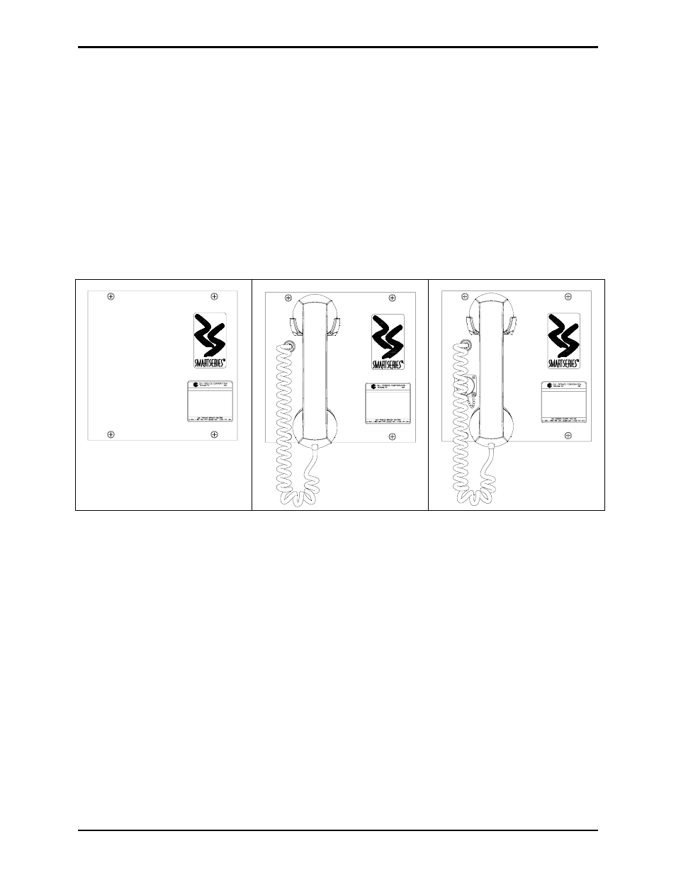
Figure 11. Model 751-901ICS
SmartSeries Speaker Amplifier
Figure 12. Model 701-902ICS
SmartSeries Handset/Speaker
Amplifier
Figure 13. Model 701-904ICS
SmartSeries Handset/Speaker
Amplifier with Auxiliary Jack
Opening and Closing the Amplifier
The setting and adjustments vary with each model. Refer to the appropriate section of this manual for the
specific instructions for the applicable model. In some cases, the amplifier must be opened to gain access
to the PCBAs inside. Opening and closing the amplifier is as follows:
1. Place the amplifier on a flat surface and loosen, but do not remove, the two sets of rear cover screws
located on the top and bottom L-shaped slots. See Figure 14.
2. Slide the front panel with the screws sideways and then pull up to separate the front panel from the
rear section. The two sections are connected by a ribbon cable.
3. Lay the rear section to the left and the front section to the right with the PCBAs facing upward for
access to the applicable adjustments.
4. After the adjustments and settings have been made, slide the rear cover L-shaped slots over the top
and bottom screws ensuring no cables are being pinched. Tighten the screws.
- 701-302ICSVC ICS AC-Powered Page/Party Plug-in Amplifiers 701-304ICSVC ICS AC-Powered Page/Party Plug-in Amplifiers 701-904ICS ICS AC-Powered Page/Party Plug-in Amplifiers 751-001ICSVC ICS AC-Powered Page/Party Plug-in Amplifiers 701-304ICS ICS AC-Powered Page/Party Plug-in Amplifiers 701-902ICS ICS AC-Powered Page/Party Plug-in Amplifiers 751-001ICS ICS AC-Powered Page/Party Plug-in Amplifiers 751-901ICS ICS AC-Powered Page/Party Plug-in Amplifiers 701-307ICS ICS DC-Powered Page/Party Plug-in Amplifiers 701-307ICSVC ICS DC-Powered Page/Party Plug-in Amplifiers 701-309ICSVC ICS DC-Powered Page/Party Plug-in Amplifiers 701-909ICS ICS DC-Powered Page/Party Plug-in Amplifiers 751-002ICSVC ICS DC-Powered Page/Party Plug-in Amplifiers 701-309ICS ICS DC-Powered Page/Party Plug-in Amplifiers 701-907ICS ICS DC-Powered Page/Party Plug-in Amplifiers 751-002ICS ICS DC-Powered Page/Party Plug-in Amplifiers 751-902ICS ICS DC-Powered Page/Party Plug-in Amplifiers