Setting the address – GAI-Tronics 701-302ICS ICS AC-Powered Page/Party Plug-in Amplifiers User Manual
Page 13
Pub. 42004-730L2B
ICS AC-Powered Page/Party
®
Plug-in Amplifiers
Page: 11 of 20
f:\standard ioms - current release\42004 instr. manuals\42004-730l2b.doc
04/11
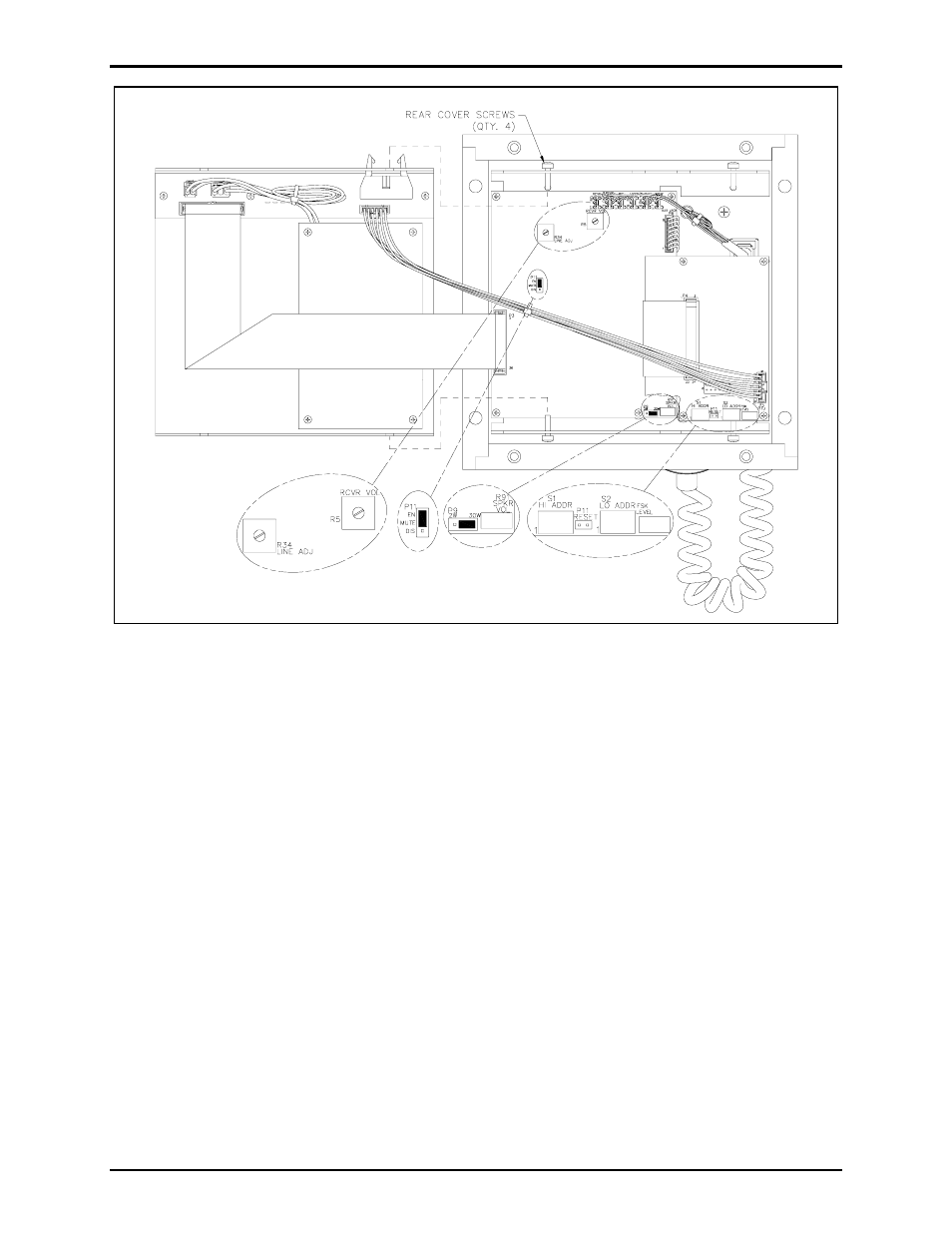
Figure 14. SmartSeries PCBA
Setting the Address
For the SmartSeries option to function properly, each station in an ADVANCE system zone must be
given a unique address using the hexadecimal switches, S1 (Hi Address) and S2 (Lo Address). Each
switch contains 16 settings, labeled 0–F. A small arrow on each switch indicates the setting.
Make a note of the address of the existing amplifier and use the same setting for the replacement
amplifier. The address settings are accessed through holes in the bottom of the ICS SmartSeries
Replacement Amplifier.
The station address is determined by the high address setting followed by the low address setting. For
example, to assign an address of 05, the high station address is set to 0 and the low address is set to 5.
Valid address settings are 05 to FE. If the SmartSeries PCBA is installed in a system without an
ADVANCE head end, set the address to 04 (default).
- 701-302ICSVC ICS AC-Powered Page/Party Plug-in Amplifiers 701-304ICSVC ICS AC-Powered Page/Party Plug-in Amplifiers 701-904ICS ICS AC-Powered Page/Party Plug-in Amplifiers 751-001ICSVC ICS AC-Powered Page/Party Plug-in Amplifiers 701-304ICS ICS AC-Powered Page/Party Plug-in Amplifiers 701-902ICS ICS AC-Powered Page/Party Plug-in Amplifiers 751-001ICS ICS AC-Powered Page/Party Plug-in Amplifiers 751-901ICS ICS AC-Powered Page/Party Plug-in Amplifiers 701-307ICS ICS DC-Powered Page/Party Plug-in Amplifiers 701-307ICSVC ICS DC-Powered Page/Party Plug-in Amplifiers 701-309ICSVC ICS DC-Powered Page/Party Plug-in Amplifiers 701-909ICS ICS DC-Powered Page/Party Plug-in Amplifiers 751-002ICSVC ICS DC-Powered Page/Party Plug-in Amplifiers 701-309ICS ICS DC-Powered Page/Party Plug-in Amplifiers 701-907ICS ICS DC-Powered Page/Party Plug-in Amplifiers 751-002ICS ICS DC-Powered Page/Party Plug-in Amplifiers 751-902ICS ICS DC-Powered Page/Party Plug-in Amplifiers