GAI-Tronics ILD1000A Local Deskset User and Installation Manual User Manual
Page 16
Installation
ILD1000A Local Desk Set
02/12 12
Terminal Strip Table
TS1
Terminal
Wire
Color
Function
1
Red
The dc power positive (+) input
2 Orange
RX
audio
3
Yellow
RX audio return
4
Shield
TX audio return
5 Brown TX
audio
6
White
Monitor output (active low)
7
Green
PTT output (active low)
8
Black
The dc power negative (–) and surge/logic ground
N
OTE
: RX and TX audio return (from all desk sets) must be connected to ground (or return) at the base
station and NOT grounded at the desk set(s).
Local Desk Set to MCS 2000 Radio Connection Chart
TS1
Pin #
Desk Set
Function
Wire
Color
Radio
Connector Pin #
Radio Function
1
DC+ power input
Red
14
Switched B+ when radio is on
2
RX audio +
Orange
11
RX audio
3
RX audio –
Yellow
10
Ground
4
TX audio –
Shield
10
Ground
5
TX audio +
Brown
13
TX audio
6 monitor
White
7
monitor
7 PTT
Green
21
PTT
8
DC– power ground Black
10
Ground
N
OTE
:
All common ground connections should be made at the radio to prevent ground loops.
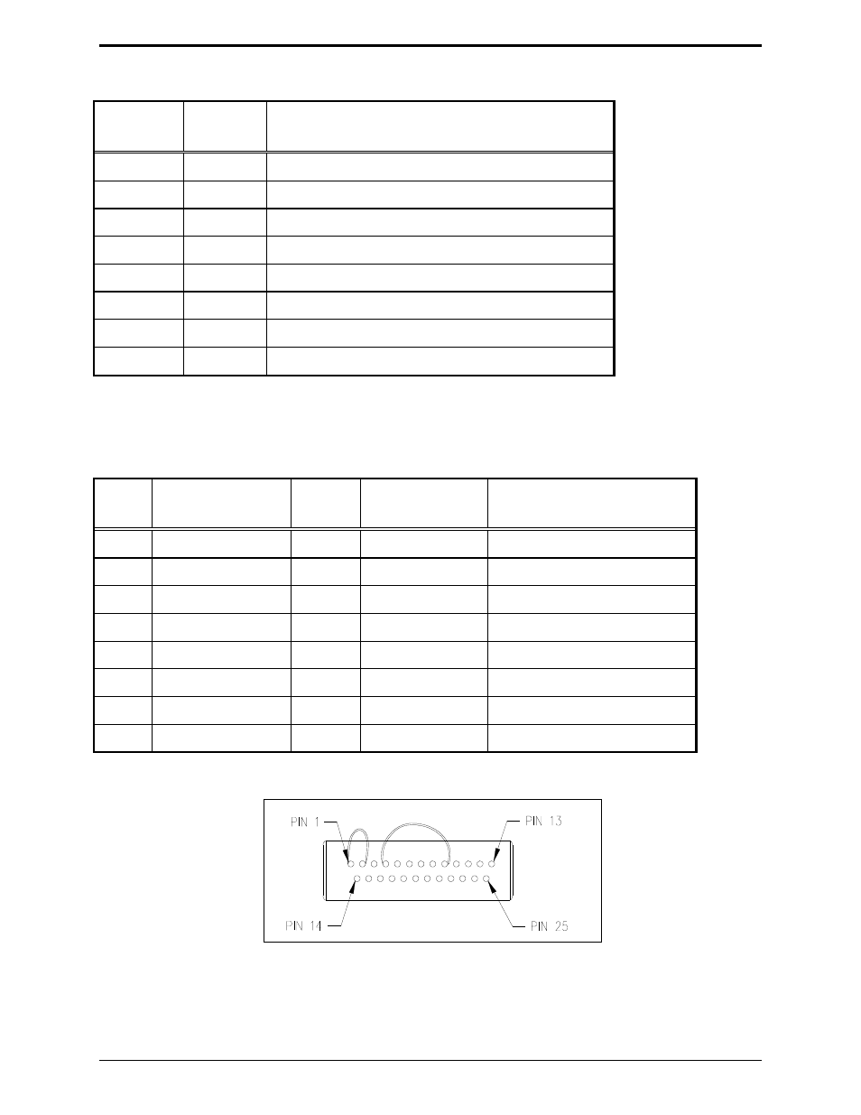
Figure 3. HLN6412 Connector Termination with
Internal Jumpers Connecting Pins 1–2 and Pins 4–9.