GAI-Tronics MI05-101 Merge / Isolate Cabinet with External Option User Manual
Page 5
Pub. MI05-101iom.2
Model MI05-101 Merge/Isolate Cabinet
Page: 5 of 24
\\86h27g1-fs\iomdocs\opnotes -- released\mi05-00x merge-isolate cabs\mi05-101.dir\mi05-101iom2.doc
01/09
If using GAI-Tronics system cable to connect field stations, terminate the ac power conductors to the
terminal blocks provided at the bottom of the cabinet. Three terminal blocks are provided for each zone.
The ac power conductors are color-coded black (H), white (N), and green (GND).
N
OTE
: These terminals do not provide power to the field station. The terminals are provided only for
convenience in terminating the system cable power conductors.
Connecting Model MS05-101 Desktop Master Stations (or equivalent)
1. Locate the Termination PCBA in the lower left corner of the cabinet. See Figure 2.
2. Connect the desktop master station to TB6 in the cabinet. The recommended cable for this
connection is a 9-pair cable.
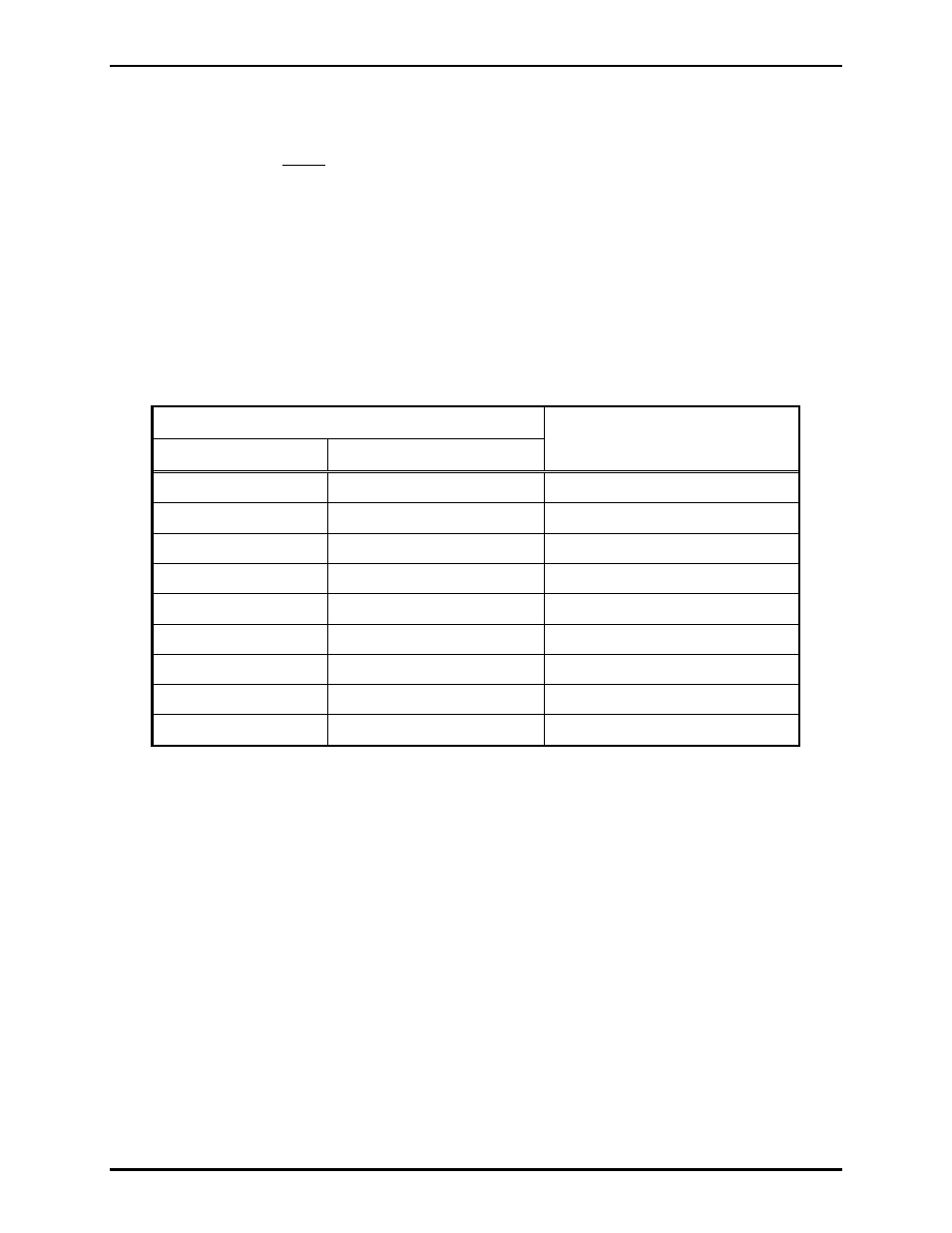
3. Make the following connections:
Terminals
Master Station
Merge/Isolate Cabinet
Function
TB3-23 and TB3-24
TB6-1 and TB6-2
RS-485 data line (+/-)
TB3-25
TB6-3
Data ground
TB1-10 and TB1-11
TB6-5 and TB6-6
Page monitor
TB1-8 and TB1-9
TB6-7 and TB6-8
Page
TB2-12 and TB2-13
TB6-9 and TB6-10
Party Line 1
TB2-14 and TB2-15
TB6-11 and TB6-12
Party Line 2
TB2-16 and TB2-17
TB6-13 and TB6-14
Party Line 3
TB2-18 and TB2-19
TB6-15 and TB6-16
Party Line 4
TB2-20 and TB2-21
TB6-17 and TB6-18
Party Line 5