Display, Normal operation (j19 = run), Scroll button and display mode – Greenheck Vari-Green Control - Indoor Air Quality - VOC (I475407) User Manual
Page 4: Wiring, Optional remote override, Optional voc level output reference
4
Display
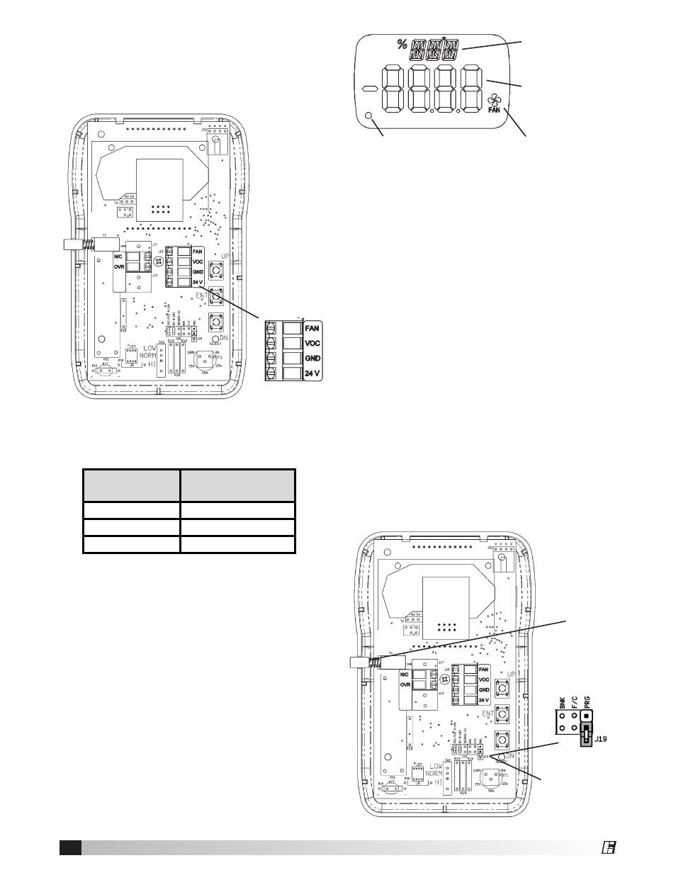
On the front of the controller is a two-line display.
The Minor Display describes the units or variable
that is being displayed. The Main Display shows the
numeric value. The Fan Icon is illuminated whenever
the Fan Speed Output voltage is at or above the
Output Minimum (as specified in parameter P7).
The dot in the lower left is used to signal Fan Cutout
Mode.
Normal Operation (J19 = RUN)
The Air Quality Controller ships from the factory set
to control VOCs to 40% contamination – the display
indicates the measured VOC Level (%VOC), the
Fan Speed Output spans 2 to 10 Volts and the Fan
Cutout Mode is disabled.
Scroll Button and Display Mode
The controller ships from the factory with the display
set to indicate the measured VOC Level (%VOC).
Pressing the scroll button at any time switches the
display to the Air Quality Setpoint (%SET). A second
push of the scroll button switches the display to the
Fan Speed in percent (%SPD), and a third push
returns the display to the VOC Level (%VOC).
Minor Display
0.34 inch 3-digit
Alpha-Numeric
Main Display
0.76 inch 4-digit
Numeric
Dot for Cutout Mode
Controller
Terminal
Transformer
Control Terminal
J15-FAN
0 to 10V
J15-GND
COM
J15-24V
24V
Wiring
All wiring for the Greenheck Air Quality Controller is
Class II low-voltage control wiring. See the Wiring
Diagram on Page 7 for the wiring overview.
Optional Remote Override
To add a Remote Override, connect a normally-open
switch between terminals J17-OVR and J15-GND
on the controller. (See Wiring Diagram on pg. 7.)
Closing this switch will activate the Remote Override
feature. Opening the switch will deactivate the
override.
Optional VOC Level Output
Reference
The VOC level is available an output signal of 0 to
10VDC from J15-VOC to J15-GND. (See Wiring
Diagram on pg. 7.) The signal is the 0 to 100% VOC
level.
Control box to factory mounted
transformer control input.
J15
Scroll
Button
Programming
Jumper in
RUN Mode
Fan Icon