Greenheck Vari-Green Control - Indoor Air Quality - VOC (I475407) User Manual
Page 6
6
Fan Cutout, Parameter P3
Factory Default = 0
0 – Fan Cutout Disabled
1 – Fan Cutout Enabled
The Fan Cutout is designed to shut off the exhaust
fan when the VOC level falls below the Air Quality
Setpoint.
With the Fan Cutout Enabled, when the %VOC
measurement is 2% below the Air Quality Setpoint
(as set by Parameter P0), the Fan Cutout timer is
activated and the dot on the display will flash. After
the Cutout Time has elapsed (as set by Parameter
P4), the Fan Speed Output on the controller will go
to 0 Volts, shutting off the exhaust fan. The Fan Icon
on the display will extinguish and the Dot will be on
steady.
When the %VOC measurement rises 5% above the
Air Quality Setpoint, the controller leaves Fan Cutout
mode and returns to normal operation. The Dot will
extinguish and the Fan Icon will turn on.
Fan Cutout Timer, Parameter P4
Factory Default = 30 Seconds
0 to 300 seconds in 1 second increments
See Parameter P3 for operational details
Output Override Percent, Parameter P5
Factory Default = 100%
20% to 100% in 1% increments
During normal operation, when the remote override
switch is closed, the Fan Speed Output on the
controller will immediately ramp to the P5 Output
Override Percent and stay there until the remote
override switch is opened. The remote override
can be activated by any normally-open voltage-free
contact. (See Wiring Diagram on pg. 7.) Closing the
contact will activate the override.
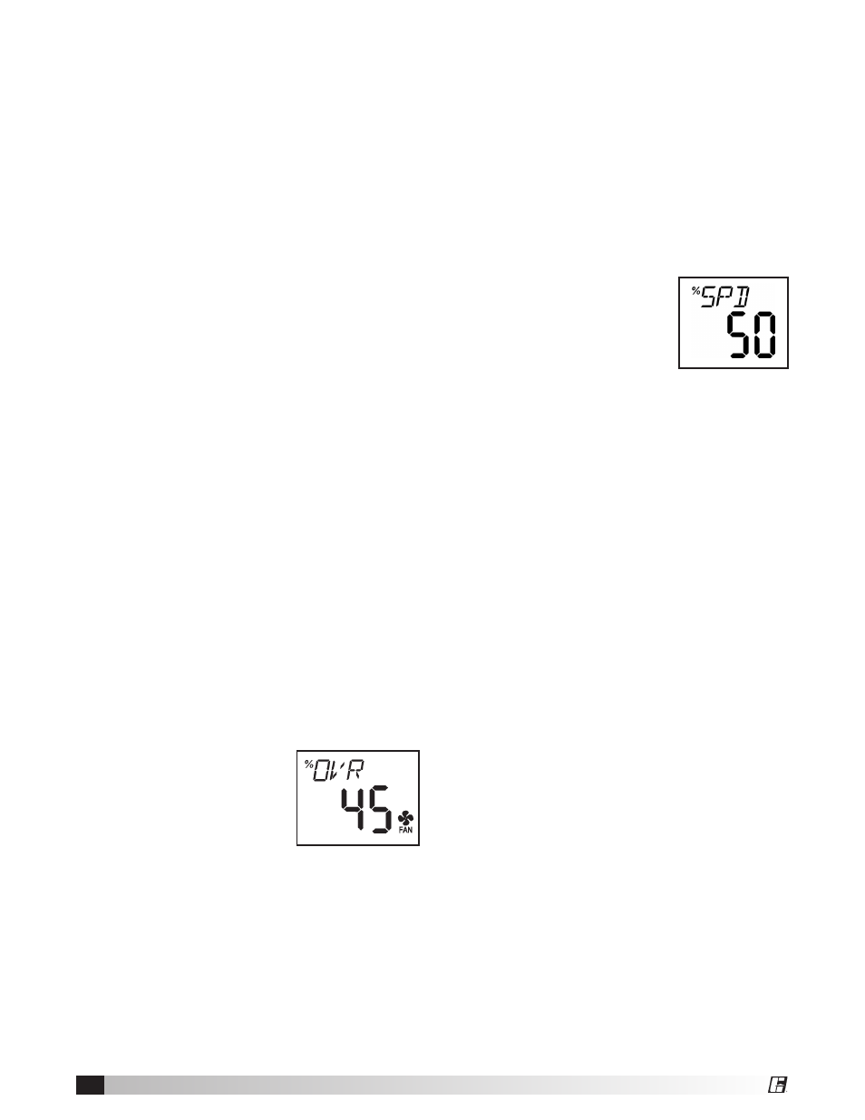
When the override is activated, the Fan Icon on the
display will turn on and the
minor display will show %OVR
and the main display will show
the Fan Speed Output percent
value.
Output State, Parameter P6
Factory Default = 1
0 – Manual Control
1 – Normal Operation
The Output State allows manual control of the Fan
Speed for system setup and commissioning tests.
Exiting this parameter returns the controller to
normal operation.
When entering this parameter, the value will be 1
(normal operation). Press the Down program switch
to set the parameter value to 0 and then press the
Enter program switch. The unit is now in Manual
Control.
The major display will read 50 for
50% output (5 VDC output). The
minor display will show %SPD.
Pressing the Up program switch
increases the displayed value
and proportionally increases the
Fan Speed Output from the controller. Pressing the
Down program switch decreases the displayed value
and proportionally decreases the Fan Speed Output.
The Fan Speed can be set to any value from 20% to
100% (for 2 to 10 VDC Fan Speed Output) or it can
be set to 0 for 0 VDC Fan Speed Output.
The Fan Speed will remain at the displayed value
until the Output State Parameter is returned to
Normal Operation mode.
Output Minimum, Parameter P7
Factory Default = 20%
20 to 100% in 1% increments
Sets the controller’s minimum Fan Speed Output
level.
Note: the controller will not allow the output minimum
to be set higher than the output maximum.
Output Maximum, Parameter P8
Factory Default = 100%
20 to 100% in 1% increments
Sets the controller’s maximum Fan Speed Output
level.
Note: the controller will not allow the output
maximum to be set lower than the output minimum.