Ordering information – Hypertherm HT4001 User Manual
Page 10
1-5
HT4001
ORDERING INFORMATION
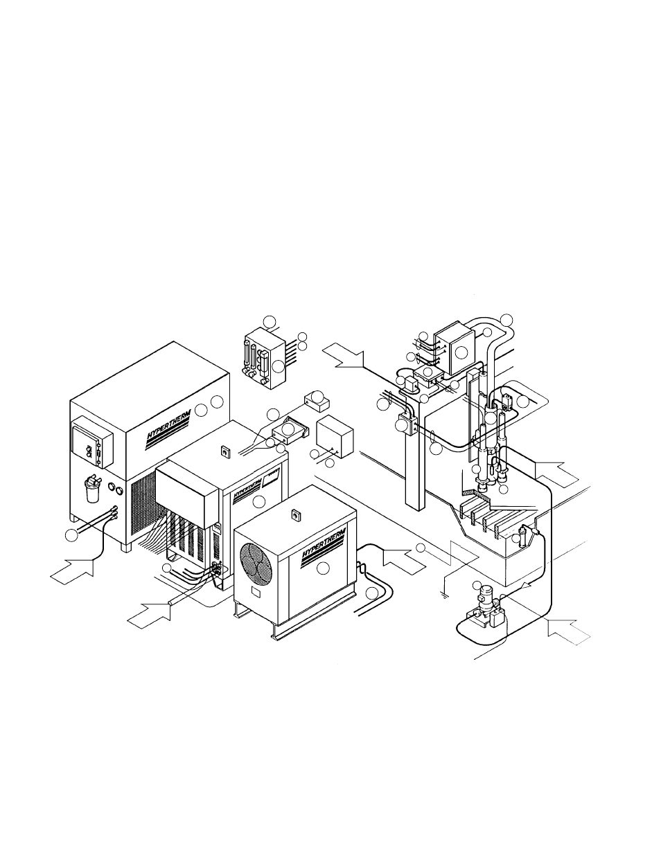
To configure an HT4001 system for a particular site, use the following steps as a guide.
In this section, each numbered step is cross-referenced in four areas: in the sample gantry
system diagram below; in block diagrams to clarify interfacing components; in the accompa-
nying parts list; and in the specifications section to clarify size and weight of major compo-
nents. (Block diagrams are offered to clarify connection points and do not necessarily reflect
relative sizes or distances between components.) At the end of this section are sample
HT4001 configurations.
Note: If the cutting system has a power track for cabling and hosing, be certain to see the
Specifications section to check hose, cable and connector diameters.
Figure 1-3 HT4001 System in a Gantry Layout
Air
Power
Power
Water
Air
3
4
5
6
8
10
11
12
13
15
6
16
17
18
19
21
22
23
28
28
28
30
30
30
31
32
14
9
28
26
23
2
1
24
25
26
29
Power