W-m supply motor valve console, Timer/ counter gas console, Machine computer interface – Hypertherm HT4001 User Manual
Page 32: Water chiller, Rhf console, Ht4001 power supply ihs console w-m air control, H401 slave, Sample system: one-torch, 750 amp
1-27
HT4001
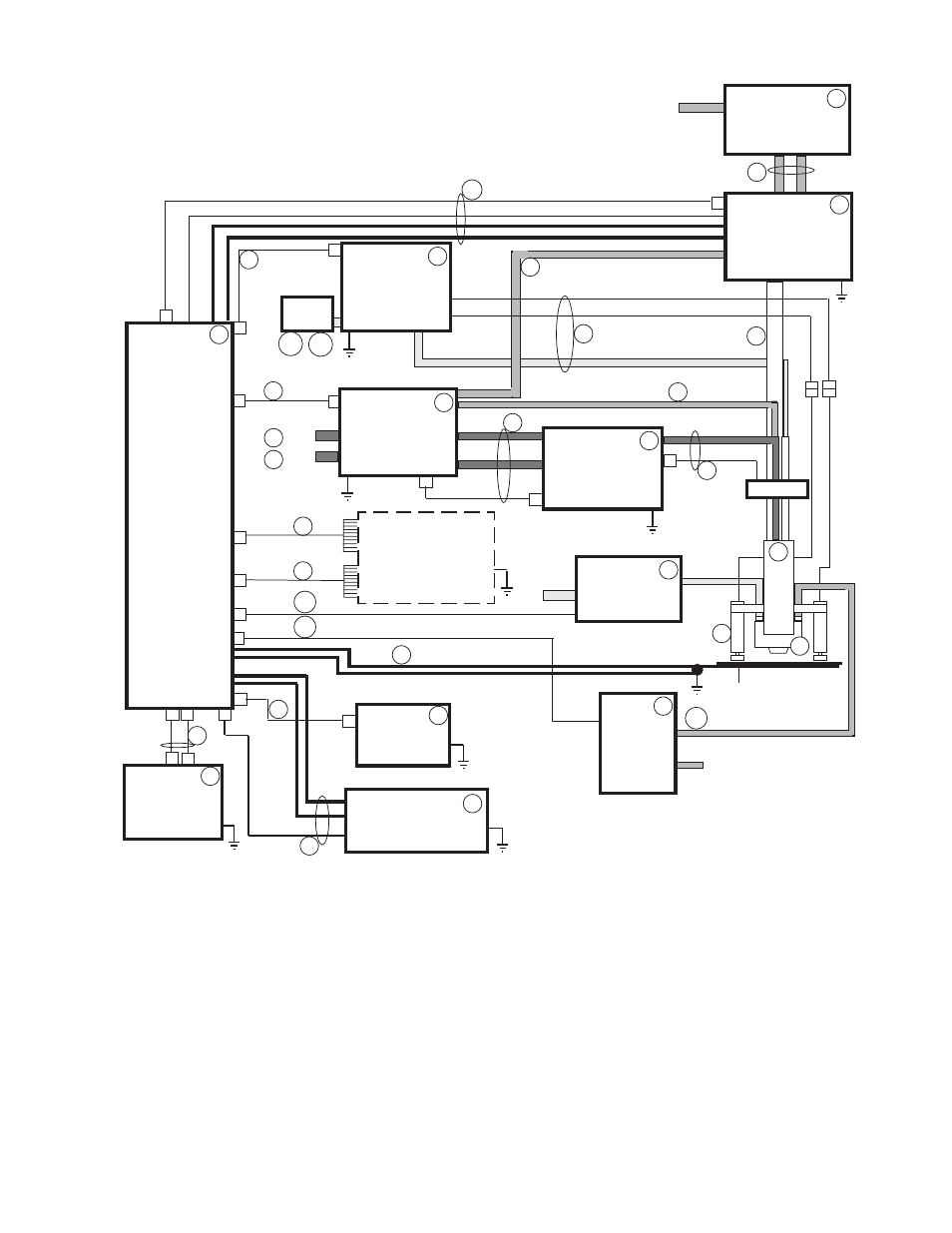
Figure 1-15 One - Torch 750 Amp HT4001 Interconnect System Diagram with IHS,
Programmable Remote and Water Muffler
H
2
O
in
1234
1234
1234
1234
1234
1234
1234
1234
1234
1234
1234
1234
1234
1234
1234
1234
1234
1234
1234
1234
1234
1234
1234
1234
1234
1234
1234
1234
1234
1234
1234
1234
1234
1234
1234
1234
1234
1234
1234
1234
1234
1234
1234
1234
1234
Work table
W-M
Supply
Motor
Valve
Console
Off Valve
Timer/
Counter
Gas
Console
N
2
in
O
2
in
31
Machine
Computer
Interface
Air in
32
10
28
2
3
4
5
9
B
11
12
13
15
14
16
17
21
22
23
Water
Chiller
24
RHF
Console
8
29
30
30
30
B
30
A
6
7
6
HT4001
Power
Supply
IHS
Console
W-M
Air Control
1
29
Air
Reg.
28
28
A
28
B
6
26
19
H401
Slave
30
30
C
Water In
(from water table)
1
HT4001 Power Supply
2
H401 Slave Power Supply
3
Slave Interconnect Kit
4
Timer/Counter
5
Timer/Counter Cable
6
Torch Assembly
8
RHF Console
9
B
Leads Between PS (w/Slave) and RHF Csl
10 Shielded Leads Between RHF Csl and Torch
11 Gas Console
12 Motor Valve Console
13 Leads Between Gas Csl and Mtr Vlv Csl
14 Water Inj. Hose Between Gas Csl and RHF Csl
15 Water Inj. Hose Between Gas Csl and Torch
16 Cable Between Gas Csl and HT4001 PS
17 Programmable V/C Control
19 Cables Between Programmable Remote and PS
21 I/O Cable Between PS and Mach. Comp.
22 V/C Cable Between PS and Mach. Comp.
23 Cable Between PS and Work Table (x2 w/Slave)
24 Water Chiller, 1-Torch, 1000A
26 Cooling Hose Set-Water Chiller to RHF Console
28 Ind. Initial Height Sensing System
28
A
Ind. IHS Regulator, Air
28
B
Ind. IHS Regulator Mounting Bracket
SAMPLE SYSTEM:
One-Torch, 750 Amp
29 Inductive IHS Lead Set
30 Water Muffler System
30
A
Addtnl Lngth WM Cable-PS to Air Cntrl
30
B
Addtnl Lngth WM Cable-PS to Pump
30
C
Addtnl Lngth WM Hose
31 Hose Between O2 Supply and Gas Csl
32 Hose Between N2 Supply and Gas Csl