IDK MSD-54 Series User Manual
Page 195
195
■MSD-5402, MSD-5402SL
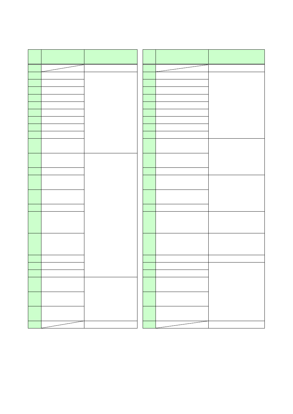
[Table 8.24] MSD-5402 and MSD-5402SL: Parallel input connectors by default
Pin
No.
Description
Function
Pin
No.
Description
Function
1
No Connection
26
No Connection
2
OUT1-IN1
*2
Selecting input
channel of OUT1
*1
27
COMMAND A
Sending control
commands
3
OUT1-IN2
*2
28
COMMAND B
4
OUT1-IN3
*2
29
COMMAND C
5
OUT1-IN4
*2
30
COMMAND D
6
OUT1-IN5
*2
31
COMMAND E
7
OUT1-IN6
*2
32
COMMAND F
8
OUT1-IN7
*2
33
COMMAND G
9
OUT1-IN8
*2
34
COMMAND H
10
OUT1-IN9
*2
35
COMMAND I
11
OUT1-OFF
36
AUDIO-OUT1 UP/
Phase A
Audio output level of
OUT 1
*4
12
OUT2-IN1
*2
Selecting input
channel of OUT2
*1
37
AUDIO–OUT1
DOWN/B
13
OUT2-IN2
*2
38
AUDIO-OUT1 MUTE
14
OUT2-IN3
*2
39
AUDIO-OUT2 UP/
Phase A
Audio output level of
OUT 2
*4
15
OUT2-IN4
*2
40
AUDIO–OUT2
DOWN/ Phase B
16
OUT2-IN5
*2
41
AUDIO-OUT2 MUTE
17
OUT2-IN6
*2
42
DISPLAY1
POWER ON/OFF
Controlling display
device power of OUT 1
*5
18
OUT2-IN7
*2
43
DISPLAY2
POWER ON/OFF
Controlling display
device power of OUT 2
*5
19
OUT2-IN8
*2
44
PARALLEL LOCK
Locking parallel input
*6
20
OUT2-IN9
*2
45
NOT USE
Not assigned
21
OUT2-OFF
46
NOT USE
22
SWITCHING–
V&A
Selecting channel
switching mode
*3
47
NOT USE
23
SWITCHING–
VIDEO
48
NOT USE
24
SWITCHING–
AUDIO
49
NOT USE
25
GND
50
GND
*1
Channels (video/audio) to be switched depend on the channel switching mode selected.
*2
If you want to switch the selected channel and turn “OFF” alternately, set “8.14.6 Toggle“ to “ON”.
If you want to perform automatic measurement of input timing setting, set “8.14.9 Analog input
measurement“ to “ENABLE” and press one of IN6 to IN9 keys for 2 seconds or longer. For details of
automatic measurement, see “8.6.6 Analog input automatic measurement”.
*3
Channel switching modes of the front panel and parallel input are independent from each other. If you want