Settings, Position the stop collar, Using the stop-collar setting block – Kreg Jig K5 User Manual
Page 5: Adjust the clamp assembly
www.kregtool.com
800-447-8638
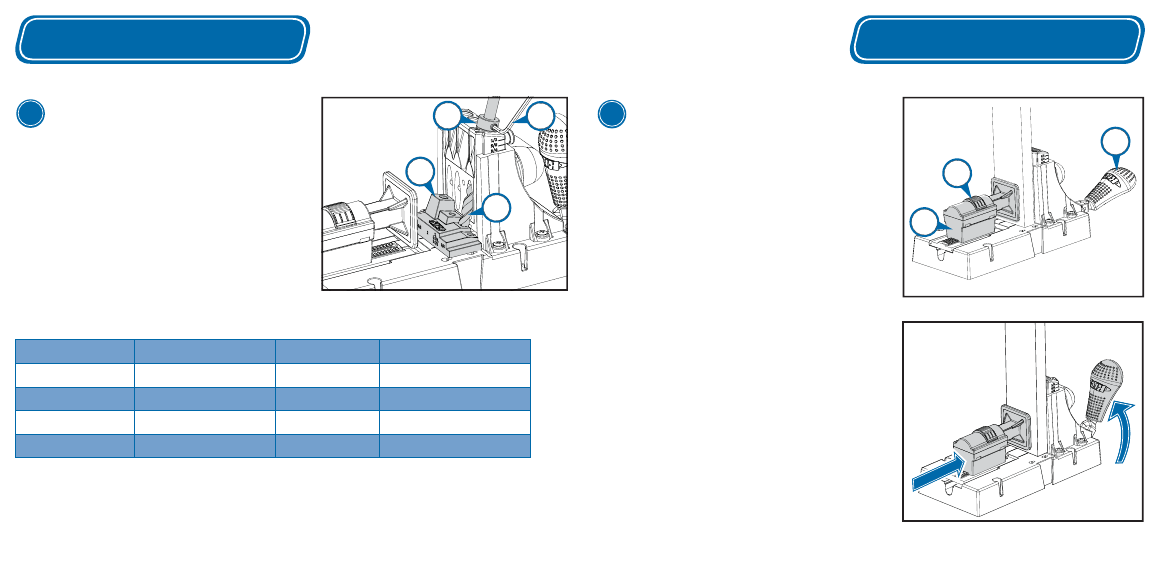
Position the Stop Collar
Place the stop-collar setting block (L) on the jig base in
front of the drill guide. Slide the step bit (I) into one of
the drill guide bushings and drop the pilot tip into the
hole in the block that corresponds to the length of the
screw you’ll be using. With the step bit shoulder resting
on the block, slide the stop collar (J) onto the drive-end
of the bit so it rests on the drill guide. Tighten the stop
collar set screw with the hex wrench (K).
Using the Stop-Collar Setting Block
*optional accessories
Settings
Adjust the Clamp Assembly
Press down on the ratchet release (F) and slide the
clamp assembly (D) all the way back. Position the
workpiece against the drill guide. Move the toggle
handle (C) to the full-down (clamped) position.
Slide the clamp assembly forward until the pad
contacts the workpiece. (You’ll hear the adjustment
mechanism clicking.)
Holding the clamp assembly against the workpiece,
raise the toggle handle until you hear the adjustment
mechanism click two times. Place the workpiece
against the drill guide and move the toggle handle
to the clamped position. Check to make sure the
workpiece is securely held in place. If needed,
raise the toggle handle one more click. The clamp
assembly is now positioned so the internal spring
applies suffi cient pressure to secure the workpiece
when the toggle handle is in the full-down position.
4
C
F
D
Example:
3
⁄
4
" board
Settings
3
K
J
I
L
Example:
3
⁄
4
" board, 1
1
⁄
4
" screw
Drill Guide & Bit
Material Thickness
Screw Length
Setting Block Step
Micro*
½"
¾"
¾"
Micro* & Standard
⅝" - 1⅛"
1", 1¼", 1½"
1", 1¼", 1½"
Standard
1¼" - 1⅜"
2"
2"
Standard & HD*
1½"
2½"
2½"