Pc connection, Connecting an antenna, Digital audio input – Marantz NA7004 User Manual
Page 11: Fm/am, Cables used for connections
5
ENGLISH
Getting Started
Connections
Connections
Basic Operations
Advanced Operations
Troubleshooting
Explanation terms
Information
Specifi
cations
Index
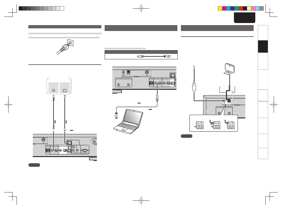
When connecting the optical digital output connector
with an optical transmission cable (sold separately)
Match the shapes then insert fi rmly.
Digital audio input
If a device equipped with CD transport or digital audio output is
connected to this unit, this unit can be used as a D/A converter.
(“Using as a D/A converter” (vpage 19))
M-XPort
DIGITAL OUT
DIGITAL IN
COAXIAL OPTICAL
OPTICAL
COAXIAL
USB
FLASHER
RS232C
IN
OUT
IN
REMOTE CONTROL
NETWORK
COAXIAL
OUT
OPTICAL
OUT
Signal fl ow
Signal
fl ow
Optical digital
connection cable
(Sold separately)
Coaxial digital
connection cable
(Sold separately)
CD Transport /
digital device
NOTE
• Linear PCM signals with a sampling frequency of 32kHz, 44.1kHz,
48kHz, 64kHz, 88.2kHz, 96kHz, 176.4kHz, or 192kHz can be input
into this device.
• Do not input signals other than linear PCM signals, such as Dolby
digital, DTS, AAC etc. into this device. Doing so may cause noise,
which may cause damage to the speakers.
PC connection
By connecting a computer to the USB port on the rear panel of this
unit using a commercially available USB connecting cable, this unit can
be used as a D/A converter. (“Using as a D/A converter” (vpage 19)
Cables used for connections
Audio cable (sold separately)
USB cable
M-XPort
ANALOG OUT
R
L
DIGITAL OUT
DIGITAL IN
COAXIAL OPTICAL
OPTICAL
COAXIAL
USB
N
Signal fl ow
Signal fl ow
USB cable
(Sold separately)
Computer installed with a
media player
USB port
Plug that fi ts the shape of the
connection device connector
Type B
Type A
Connecting an antenna
FM/AM
• Connect the FM antenna or AM loop antenna supplied with the unit
to enjoy listening to radio broadcasts.
• After connecting the antenna and receiving a broadcast signal
(vpage 11 “Tuning in Broadcast Stations”), fi x the antenna with
tape in a position where the noise level becomes minimal.
ANALOG OUT
R
L
w
e
q
AM loop antenna
(Supplied)
FM indoor antenna
(Supplied)
White
Black
NOTE
• Do not connect two FM antennas simultaneously.
• Even if an external AM antenna is used, do not disconnect the AM
loop antenna.
• Make sure the AM loop antenna lead terminals do not touch metal
parts of the panel.
• If the signal has noise interference, connect the ground terminal
(GND) to reduce noise.
• If you are unable to receive a good broadcast signal, we recommend
installing an outdoor antenna. For details, inquire at the retail store
where you purchased the unit.
Digital connection
1.NA7004N_ENG_0826.indd 5
1.NA7004N_ENG_0826.indd 5
2010/08/26 19:16:07
2010/08/26 19:16:07