Ainscbg.vi – Measurement Computing UL for NI LabVIEW User Manual
Page 19
Universal Library Virtual Instruments (VIs)
Analog Input VIs
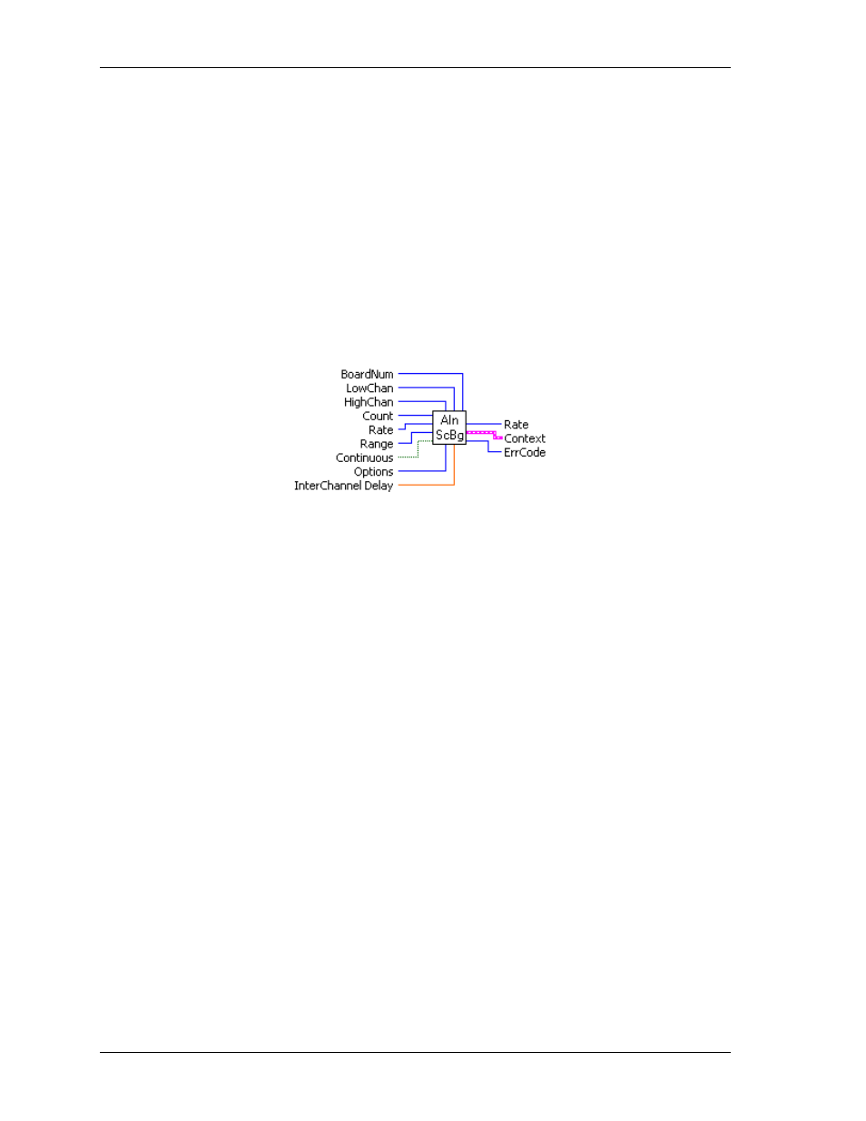
AInScBg.VI
Changed R3.3 ID, R5.4 ID'
Scans a range of A/D channels in the background and stores the samples in an array. This VI reads the
specified number of A/D samples at the specified sampling rate from the specified range of A/D channels
from the specified board. If the A/D board has programmable gain, it sets the gain to the specified range. The
collected data is returned to the data array. This VI immediately returns control to your program and the data
transfer from the A/D board into ADData will continue in the background. ADData is the array contained in
the context output. Use the GetStatus.VI to check on the status of the background operation and to get data as
it is being collected. Use StopBg.VI to terminate the background process before it has completed. Always
execute StopBg.VI after any background operation has terminated normally to clear variables and flags.
Revision 3.3: added an option to disable real-time calibration. See OptAIn.VI on page 30 for details.
Revision 5.4: added InterChannel Delay input.
Summary:
Inputs:
BoardNum
[U32] - The board number assigned when installed with InstaCal. Can
be 0 to 100.
LowChan
[I32] - First A/D channel of scan
HighChan
[I32] - Last A/D channel of scan
Count
[I32] - Number of A/D samples to collect
Rate
[I32]- Sample rate in scans per second
Range
[I32]- A/D range code
Continuous
[TF] - Run the VI in an endless loop
Options
[I32] - Bit fields that control various options.
InterChannel
Delay
[SGL] - Delay in seconds between channels in a scan.
Outputs:
Rate
[I32] - Actual rate the board sampled
Context
[cluster] - Output data structure.
ErrCode
[I32] - Error code. See ErrMsg.VI on page 97.
Arguments:
BoardNum
The board number associated with a board when it was installed with InstaCal. The
specified board must have an A/D. Can be from 0 to 100.
LowChan
First A/D channel of scan.
HighChan
Last A/D channel of scan.
Low/High Channel
#: The maximum allowable channel depends on which type of
A/D board is being used. For boards that have both single-ended and differential
inputs, the maximum allowable channel number also depends on how the board is
configured. For example, a PCI-DAS6025 has 8 channels for differential, 16 for
single-ended mode.
Count
Specifies the total number of A/D samples that will be collected. If more than one
channel is being sampled then the number of samples collected per channel is
equal to
Count
/ (
HighChan
-
LowChan
+1).
19