C9513init.vi – Measurement Computing UL for NI LabVIEW User Manual
Page 59
Universal Library Virtual Instruments (VIs)
Counter VIs
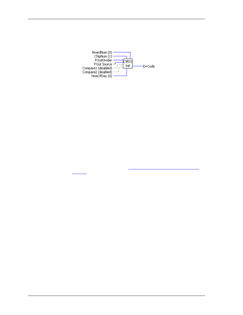
C9513Init.VI
Initializes all of the chip level features of a 9513 counter chip.
Summary:
Inputs:
BoardNum
[U32] - The board number assigned when installed with InstaCal. Can
be 0 to 100.
ChipNum
[U32] - Specifies which 9513 chip is to be initialized.
FoutDivider
[U32]
- F-Out divider (0-15)
FoutSource
[U32] - Specifies source of the signal for F-Out signal.
Compare1
[TF] - ENABLED or DISABLED
Compare2
[TF]- ENABLED or DISABLED
TimeOfDay
[U32] - DISABLED (0) or 1-3
Output:
ErrCode
[U32] - Error code. See ErrMsg.VI
Arguments:
BoardNum
The board number associated with a board when it was installed with InstaCal. The
specified board must have a 9513 counter.
ChipNum
Specifies which 9513 chip is to be initialized. For a CTR05 board, this should be
set to 1. For a CTR10 board, it should be either 1 or 2. For a CTR20, it should be 1
to 4.
Refer to board-specific information contained in the Universal Library User's
Guide (available on our we
FoutDivider
Corresponds to 9513 description in Counter Mode Register Description
0 Divide
by
16
1 Divide
by
1
2 ... 15 Divide by the number 2 ... 15
FoutSource
Corresponds to 9513 description in Counter Mode Register Description
TCPREVCTR
TCN - 1 (Terminal count of previous counter)
CTRINPUT1
SRC 1 (Counter Input 1)
CTRINPUT2
SRC 2 (Counter Input 2)
CTRINPUT3
SRC 3 (Counter Input 3)
CTRINPUT4
SRC 4 (Counter Input 4)
CTRINPUT5
SRC 5 (Counter Input 5)
GATE1
GATE
1
GATE2
GATE
2
GATE3
GATE 3
GATE4
GATE
4
GATE5
GATE
5
FREQ1
F1
FREQ2
F2
59