Doutscbg.vi – Measurement Computing UL for NI LabVIEW User Manual
Page 80
Universal Library Virtual Instruments (VIs)
Digital I/O VIs
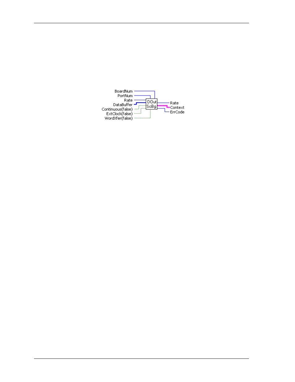
DOutScBg.VI
Performs multiple writes to the digital output port of a high speed digital port on a board with a pacer clock
like the CIO-PDMA16. When this VI is used, control will return immediately to the next point in your
program and the transfer to the digital output port from
DataBuffer
will continue in the background. Use
GetStatus.VI to check on the status of the background operation. Use StopBg.VI to terminate the background
process before it has completed. Always use the StopBg.VI after all background operations to clear variables
and flags.
Summary:
Inputs:
BoardNum
[U32] - The board number assigned when installed with InstaCal. Can
be 0 to 100.
PortNum
[I32] - Specifies the digital I/O port to set.
Rate
[U32] - Number of times per second (Hz) to write.
DataBuffer
[I16] - Digital output values.
Continuous
[TF] - Run the VI in an endless loop (True).
ExtClock
[TF] - External (True) or internal clock (False).
WordXfer
[TF] - Word (True) or byte transfer (False).
Outputs:
Rate
[I32] - Actual scan rate.
Context
- [cluster] - Output data structure.
ErrCode
[I32] - Error code. See ErrMsg.VI.
Arguments:
BoardNum
The board number associated with a board when it was installed with InstaCal.
PortNum
If the port type is not
AUXPORT
, the specified port must be configured for output.
For many boards, AUXPORT is not configurable. However, some later boards do
require that the AUXPORT be configured using DCfgPort.VI or DCfgBit.VI.
Please see board details for more information.
Rate
Number of times per second (Hz) to write to the port. The actual update rate in
some cases will vary a small amount from the requested rate. The actual rate will
be returned to the
Rate
argument.
DataBuffer
Array of digital values to output.
Continuous
This option puts the VI in an endless loop. After it transfers the required number of
bytes it resets to the start of
DataBuffer
and begins again. The only way to stop this
operation is with StopBg.VI.
ExtClock
If this option is used, then transfers will be controlled by the signal on the trigger
input line rather than by the internal pacer clock. Each transfer will be triggered on
the appropriate edge of the trigger input signal (see board-specific info). When this
option is used, the
Rate
argument is ignored. The transfer rate is dependent on the
trigger signal.
WordXfer
Normally, this VI sets a single (byte) port (default is False). If
WORDXFER
is
specified (True), it will set two adjacent ports on each write and store the value of
both ports together as the low and high byte of a single array element in
DataBuffer
[].
80