5 vs error triggered by … 3.2.6 signal integrity, 7 phase delay, 8 additional frames delay – Nevion FRS-3G-DUAL User Manual
Page 19
FRS-3G-DUAL
Rev. B
nevion.com | 19
3.2.5
VS error triggered by …
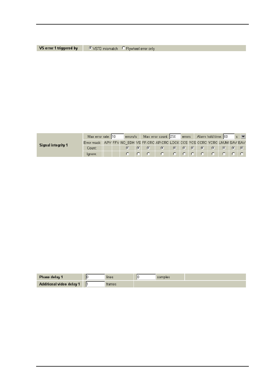
Figure 8: Multicon Gyda view of the VS error bit functionality selector
This must be seen in relation to both the Video generator block and the Signal integrity
block (next chapter). In the Signal integrity
block there’s an error bit called VS, i.e. Video
Standard error. Normally this error bit would only be asserted when the internal flywheel of
the reclocker is locked, but to an unknown video standard. When VSTD error is selected in
Video error triggered by, the Video standard setting in the Video generator block will also
act as an Expected video standard. Whenever the Expected video standard does not match
the incoming video standard (as reported in the Signal integrity block, the VS error bit will
be asserted. The VS error bit can then make the error counter in the Signal integrity block
act as a video standard alarm.
3.2.6 Signal integrity
Figure 9: Multicon Gyda view of the signal integrity block, all error bits set to count
In this block a number of standard video error bits can be set to be either counted or
ignored. The counter will count frames wit at least one error. Multiple errors in the same
frame will only be counted once, but the actual errors as reported from the module can be
seen on the module’s info page (see description in chapter 3.2.1).
3.2.7 Phase delay
This is arguably the core of the frame synchronizer. By setting the Phase delay in video
lines and video samples, the phase of the output can be adjusted relative to an incoming
sync reference. Negative delays will force start-of-frame for the output to come slightly
earlier than the reference (compensating for reference propagation time or pre-
compensating for a cable length on the output). Of course, for negative phase delays
approaching one frame, it may be more practical to imagine it as a smaller positive delay.
For practical purposes one can consider the phase delay block to be a delay line that
automatically adjusts itself between 0-1 frame to keep a constant phase between itself and
the reference. If a reference signal is not available, the delay in lines and samples will
simply be added to the frame delay in Additional video delay, and the two delays together
will act as a single constant delay line.
Figure 10: Multicon Gyda view of the delay settings
3.2.8 Additional frames delay
As mentioned the phase delay will effectively be a 0-1 frame variable delay line when a
reference is present. The Additional video delay setting will then add entire frames to this
delay, and for practical purposes an additional delay of N frames is equivalent to saying that
the phase delay will vary between N and (N+1) frames. The Additional delay setting is
useful to compensate for processing delays in other equipment (notably Dolby E
processors, if audio is split from video and embedded again at a later stage). Maximum
frame delay is 7 frames, which means that maximum total delay is 7-8 frames with
reference present.