4 gpi pin-out, 3 what the leds mean, 1 exceptions/special conditions for the leds – Nevion FRS-3G-DUAL User Manual
Page 9
FRS-3G-DUAL
Rev. B
nevion.com | 9
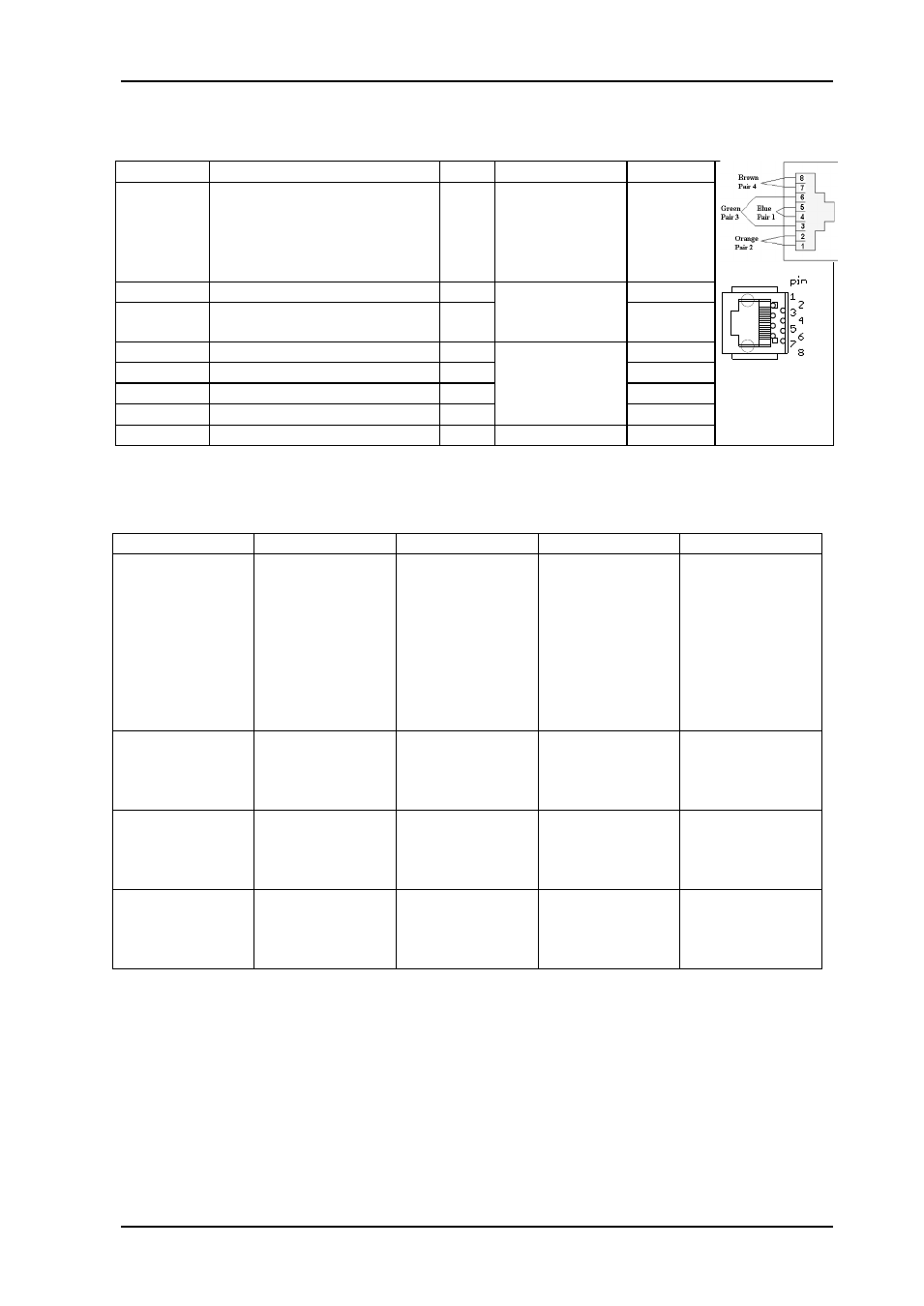
2.2.4 GPI pin-out
GPI name
Function
Pin #
Mode
Direction
GPIO 0,
Status
General error status for the
module. Will also activate at
firmware loading, when the
module is not processing
video.
Pin 1 Inverted Open
Collector
(open is alarm)
Output
GPIO 1
Not assigned
Pin 2 Inverted Open
Collector
(open is alarm)
Output
GPIO 2
Not assigned
Pin 3
Output
GPI 0
Not assigned
Pin 4
TTL, 0V =
active level
Input
GPI 1
Not assigned
Pin 5
Input
GPI 2
Not assigned
Pin 6
Input
GPI 3
Not assigned
Pin 7
Input
Ground
0 volt pin
Pin 8 0V.
Table 3: The TP45 (8pin modular jack) in detail
2.3 What the LEDs mean
Table 4: LED states and what they mean
2.3.1 Exceptions/special conditions for the LEDS
The locate command will make all four LEDs blink on and off synchronously to quickly
identify the module in a larger installation. The condition of the card is not otherwise
affected by the command, only the appearance of the LEDs will change. The LEDs return to
their normal states and functions after the special locate condition has timed out.
Red LED
Orange LED
Green LED
No light
Card status
PTC fuse has
been triggered
or FPGA
programming
has failed
Module has not
been
programmed, or
RESET and
OVR DIPS are
both on, or
module is
loading
firmware.
Module is OK
Module has no
power
IN1
Video signal
absent.
Video signal
present but card
unable to lock
VCXO
Video signal
present and
locked
Module has not
been
programmed
IN2
Video signal
absent.
Video signal
present but card
unable to lock
VCXO
Video signal
present and
locked
Module has not
been
programmed
Sync input
status
Sync signal
absent
Sync signal
present but card
unable to lock
all VCXO
B&B or Tri-level
sync in lock
Module has not
been
programmed