1 sync input, 2 gpi outputs (alarms), 3 gpi inputs – Nevion FRS-3G-DUAL User Manual
Page 8
FRS-3G-DUAL
Rev. B
nevion.com | 8
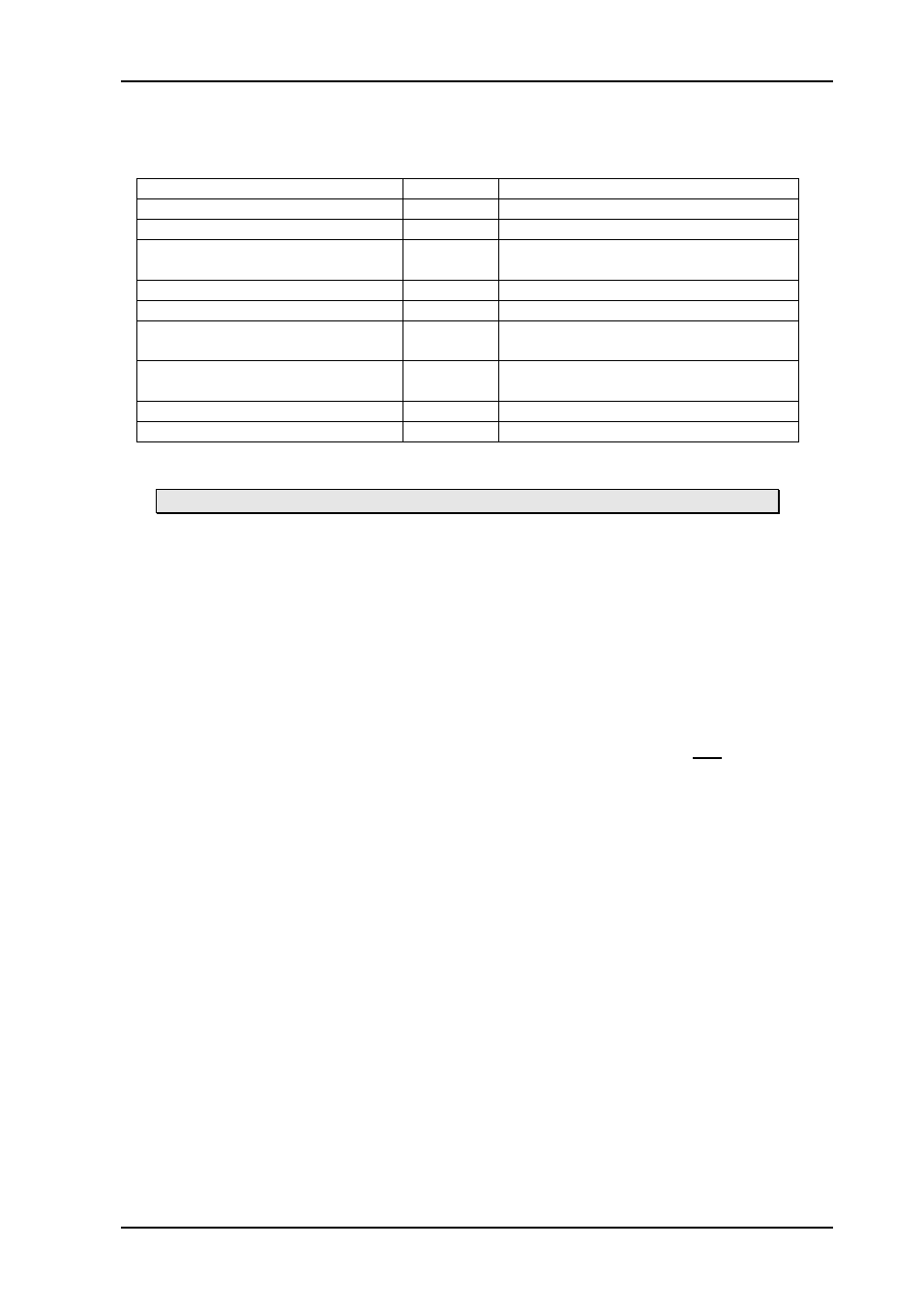
The backplane for the FRS-3G-DUAL is labeled FRS-3G-DUAL-C1. It is designed to be
fitted in a Flashlink rack unit and to take up a single slot. The table below is an overview of
the connectors and their associated functions.
Function
Label
Connector type
3G/HD/SD-SDI input
IN1
BNC
3G/HD/SD-SDI output 1
OUT1
BNC
3G/HD/SD-SDI output 1 inverted _____
OUT1
BNC
3G/HD/SD-SDI input 2
IN2
BNC
3G/HD/SD-SDI output 2
OUT2
BNC
3G/HD/SD-SDI output 2 inverted _____
OUT2
Black & Burst/ tri-level frequency
reference input
SYNC
BNC
GPI out
GPI/DATA TP45, pin 1, 2, 3 (pin 8 = GND)
GPI in
GPI/DATA TP45, pin 4, 5, 6, 7 (pin 8 = GND)
Table 2: Connector functions
Unused SDI inputs/outputs should be terminated with 75 Ohm.
2.2.1 Sync input
The main module features a slide switch to select between sync taken from the backplane
input (switch position marked “BP”) and a frame-distributed sync (switch position marked
“RACK”). At the time of writing this manual no frame-distributed sync is available, and the
switch should always
be kept in the “BP” position.
The backplane also features a switch on the component side (the side facing into the
frame). This is a switchable termination for the backplane sync input. By setting the slide
switch (marked with a yellow box in Figure 2) to the left position like pictured, the sync input
is terminated to 75 Ohm. Generally, the sync inputs should be terminated if each sync input
is fed from a separate output of a distribution amplifier. On the other hand, if one sync
output is passively split and fed to several modules (via T-connectors), only one of the
modules should terminate the sync, the others should leave it unterminated.
If the module will be used without a sync frequency reference, the positions of these slide
switches do not matter.
2.2.2 GPI outputs (alarms)
The FRS-3G-DUAL hardware module has three GPI output lines. The first one, GPIO 0,
reflects the general status of the card, and thereby acts as an all-purpose alarm. GPIO 1
and GPOI 2 reflect the reclocker lock status of inputs 1 and 2, respectively. See Table 3
below for pin-out of the GPI lines.
2.2.3 GPI inputs
The FRS-3G-DUAL hardware module has four GPI inputs. No functions have yet been
assigned to these input lines.