6 operation, 1 front panel led indicators, 2 gpi alarms – Nevion FSR-HD User Manual
Page 24: 3 gpi/ aes/ data connections 8pin modular jack, 6operation
FRS-HD
Rev. G
nevion.com | 24
6
Operation
6.1 Front panel LED indicators
Diode \
state
Red LED
Orange LED
Green LED
No light
Card status
PTC fuse has
been triggered or
FPGA
programming has
failed
Module has
not been
programmed
or RESET
and OVR
DIPS are on.
Module is
OK
Module has no
power
SDI input
status
Video signal
absent.
Video signal
present but
card not able
to lock VCXO
Video input
signal in lock
Module has not
been
programmed
Sync input
status
Sync signal
absent
Sync signal
present but
card unable
to lock VCXO
B&B or Tri-
level sync in
lock
Module has not
been
programmed
Audio input
status
No audio
embedded in
incoming video
One, two or
three audio
groups
embedded in
incoming
video
4 audio
groups
embedded in
incoming
video
Module has not
been
programmed
6.2 GPI alarms
Only three alarms are present on the RJ45 connector as two pins are used for the AES/
RS422 data port and one pin is used for Frame delay pulse signal.
The three alarms are:
- Status error
- Video signal lost
- Black and burst lost
An active alarm condition means that the transistor is conducting.
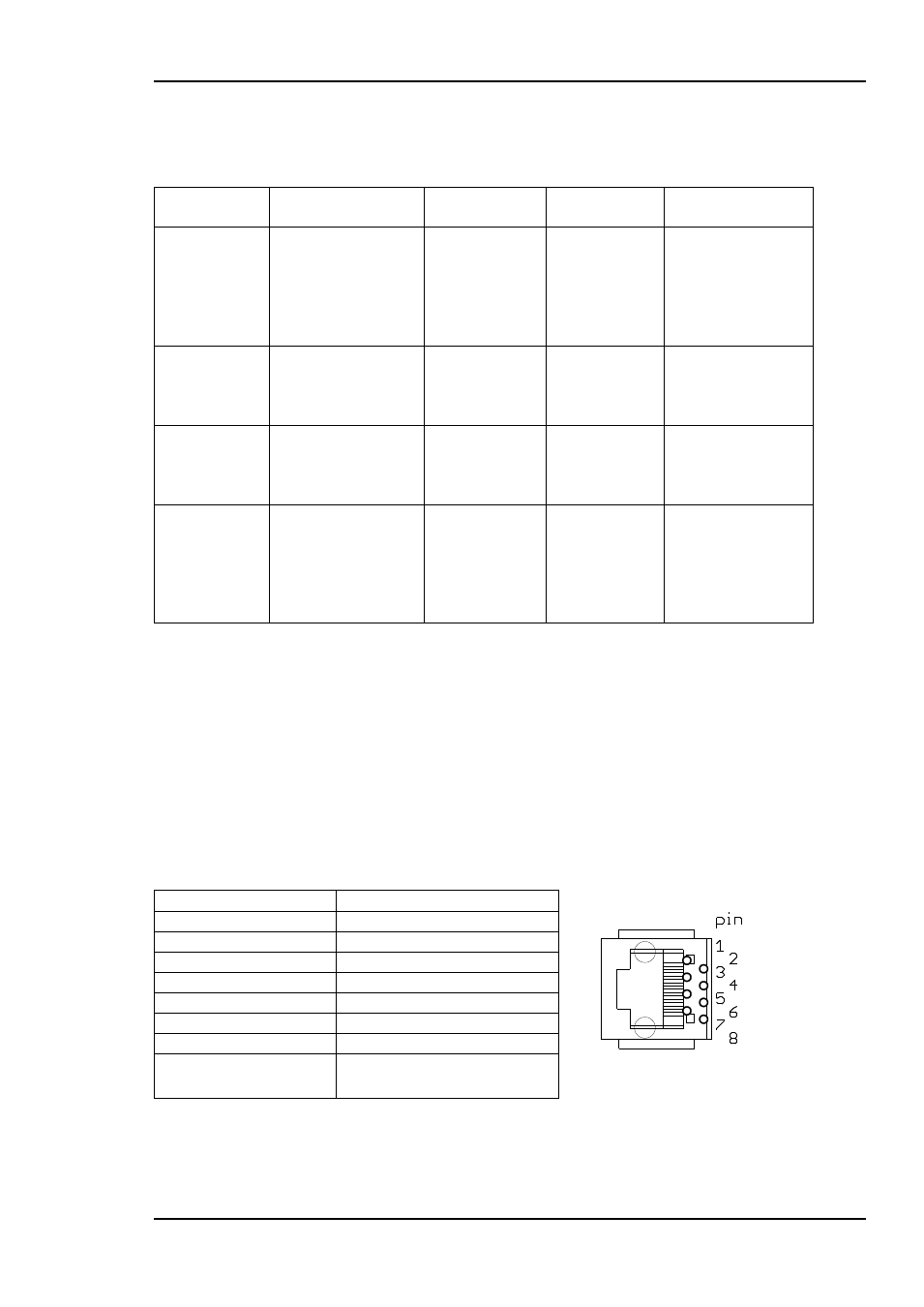
6.3 GPI/ AES/ Data connections 8pin modular jack
Pin number
Description
Figure 14: GPI pin layout
1
Status error
2
SDI input lost
3
Black & Burst lost
4
AES+/RS422+
5
Ground
6
AES-/RS422-
7
Frame delay
8
Ground