3 optical/ electrical input selection, 4 de-glitcher, 5 frame synchronizer – Nevion FSR-HD User Manual
Page 8: 1 frame sync mode
FRS-HD
Rev. G
nevion.com | 8
3.3 Optical/ Electrical input selection
The FRS-HD-DMUX has both an optical (option, see Chapter 1.1) and an electrical input.
The input can be chosen either by an automatic selection with priorities and rule of
switching or by manual selection. This feature is only available through GYDA.
Automatic selection mode
In GYDA the video in mode choice is set to auto. Three input choices can be made for
three priorities; optical, electrical or mute. This priority sets the order in which the card
will look for a valid input.
It is also possible to set a rule for when the input should be switched to the next priority.
The rules are:
lol = loss of lock
los = loss of signal
EDH = Errors are found in the video
Hold time and lock time can also be set for signals. This is described in Chapter 3.5.1.
3.4 De-glitcher
The de-glitcher corrects timing errors within a line. The de-glitcher has a 2048 samples
buffer. When the first signal is present, we call it the “initial phase signal”, data is taken
from the centre of this buffer. If the timing reference of the video signal changes, when
for instance a new source being switched into the signal path, the timing errors occurring
by this change will be corrected if the new timing reference is within +/-1024 samples of
the “initial phase signal”. This also goes for all consecutive timing references.
If a signal occurs that is more than +/-
1024 samples off relative to the “initial phase
signal”, the output will repeat the last frame, refill the 2048 samples buffer and take out
data from the centre of the buffer. This new signa
l is now considered the “initial phase
signal”.
Hence, it produces an error free video output without frame wrapping when the video
input comes from a router with synchronous input video signals that all lies within +/-
1024 samples of each other.
3.5 Frame synchronizer
The frame synchronizer consists of a frame store buffer and some control logic. The
frame store buffer can store up to 8 full HD frames. Data is fetched from this buffer
according to the user settings by force of the control logic. The control logic sets the
frame synchronizer into different modes dependent on the presence of a sync input.
3.5.1 Frame sync mode
If a sync input (B&B or Tri-level) is present, the frame synchronizer will output a signal
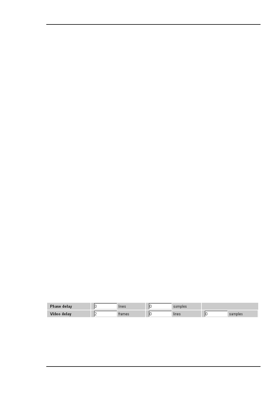
that has a delay relative to this signal. Two parameters can be set; "Phase delay" and
"Video delay".
Figure 3: Gyda view of the video delay settings
Let us first focus on the phase delay
, which also may be called “output phase delay”.
This parameter can be positive or negative, and determines the relationship between the