3 description, 1 data path, 2 video blocks overview – Nevion FSR-HD User Manual
Page 7: 3description, Frs-hd rev. g
FRS-HD
Rev. G
nevion.com | 7
3
Description
3.1 Data path
HD/SD-SDI input is selected from either optical or electrical input and equalized, re-
clocked and de-serialized and transferred to a processing unit called an FPGA. In the
FPGA the signal is first sent through a de-glitcher that cleans up errors that might appear
on lines, for instance due to switching. After the video is de-glitched, it is sent along two
paths; it is given to a frame-store buffer, and it is given to the audio de-embedder.
The 16 audio channels coming from the de-embedder are bundled in pairs and sent to
an audio store buffer. The audio is fetched from the audio store buffer according to a
user specified delay and sent to an Audio Cross Point. The audio out of the Audio Cross
Point can be any pair of audio channels de-embedded from the incoming video stream,
an internal 1
kHz sine or an internal “black sound”. “Black sound” is in function mute, but
it produces a waveform pattern on the AES output which is different from mute. From the
cross point outputs each channel pair enters an Audio Processing Block, where the
paired channels may be shuffled. After the audio processing block the audio enters the
Audio Embedder.
The video (with audio still inserted) is fetched from the frame buffer with the user
specified delay and sent to a Video processing block followed by an EDH processing
block. After the EDH block the video and audio is embedded according to the user
settings and the video is sent from the FPGA to a serializer that re-clocks the data and
output the SDI to a buffered output switch.
The buffered output switch is a 2x2 cross point with input 1 being the equalized and re-
clocked input (non-processed) and input 2 being the output of the video processing. The
two outputs are sent to two paired (non-inverting and inverting) outputs.
There are also outputs for one stereo pair of analog audio and one AES. These outputs
are taken out from the Audio cross point and can be any stereo pair of audio channels
embedded on the incoming video stream, the internal 1 kHz sine generator or the internal
“black sound” generator.
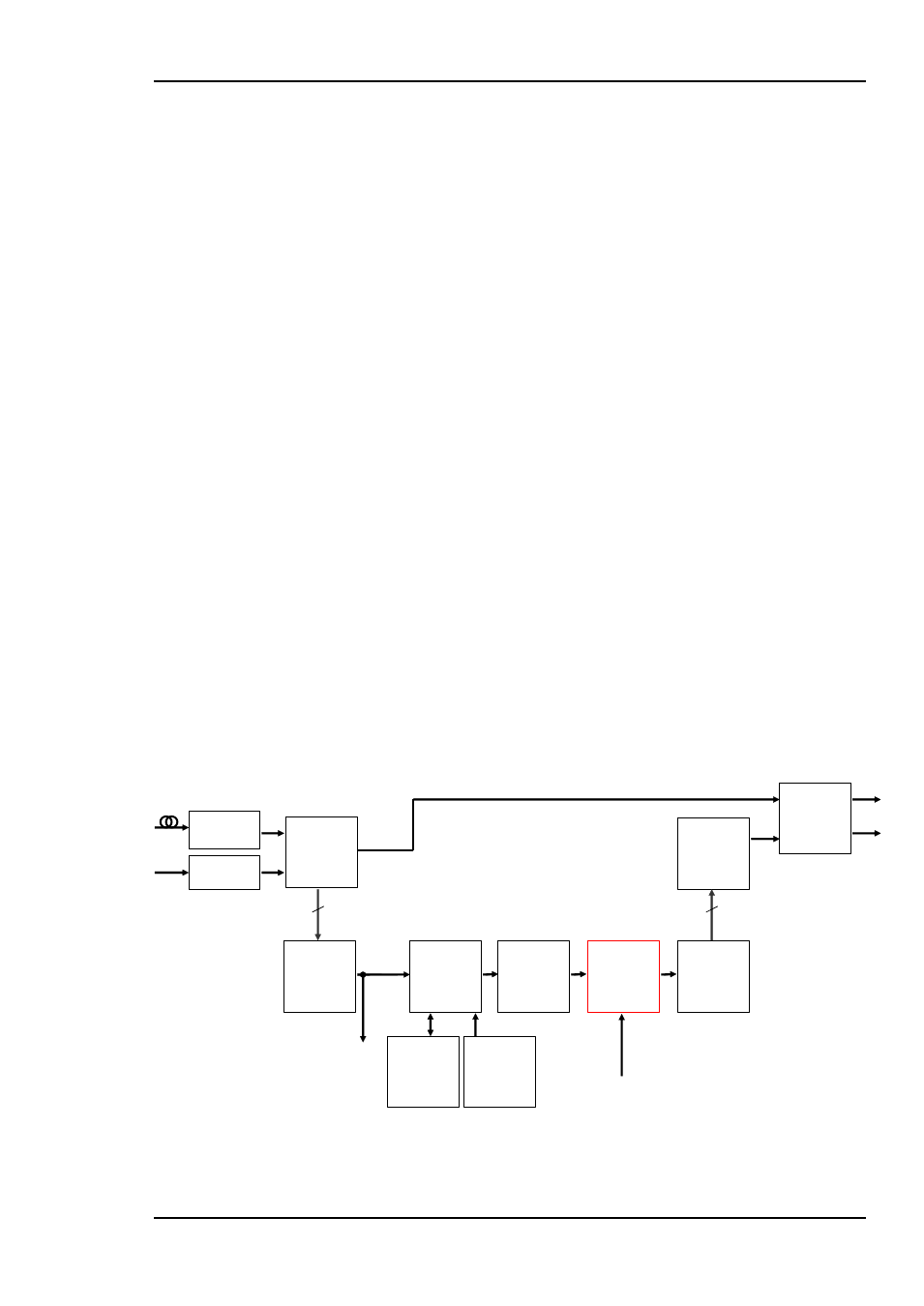
3.2 Video blocks overview
Figure 2: Video function blocks
De-glitcher
Frame sync
control logic
Video/
Audio
Frame
buffer
Video
Generator
Video
processing
Audio
embedder
Reclocker
And
De-serializer
To a
udi
o
de
-e
mb
e
dder
Optical
receiver
Cable
equalizer
From a
udio
proc
e
s
s
ing
EDH
processing
Serializer
and
reclocker
2x2
output
switch
10bit
10bit