Nevion FSR-HD User Manual
Page 9
FRS-HD
Rev. G
nevion.com | 9
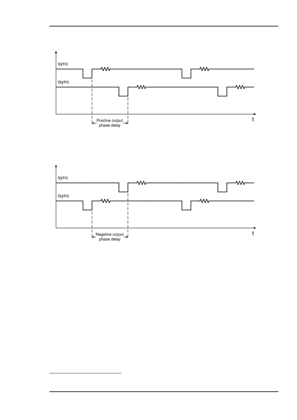
outgoing video and the sync signal. The parameter really determines a delay on an
internal sync signal, isync
1
. The output is synchronous with isync, see Figure 4.
Figure 4: Positive phase delay
Figure 4 show how the sync signal and the isync signal would look on an oscilloscope, if
converted to analogue signals. The delay of isync can be given in frames, lines, and
samples. The delay can be negative, see Figure 5.
Figure 5: Negative phase delay
The phase delay can thus be written in several ways, a large positive delay will equal a
small negative delay, because there is wrap-around on a frame basis. It follows that it is
not useful to specify a phase delay larger than 1 frame. Strictly speaking the range could
have been limited to -1/2 frame to 1/2 frame. For convenience, the delay range is allowed
to be from -1 frame + 1100 samples to 1 frame
– 1100 samples.
In order for FRS-HD-DMUX to honor the phase delay setting, it should ideally delay the
incoming video between 0 to 1 frames. Because the processing delay through the card
is 2 lines minimum, the actual window is between 2 lines and 1 frame + 2 lines. Hence,
with the parameter (minimum) video delay set to 2 lines (the least number possible for
the parameter); the output video will be between 2 lines and 1 frame + 2 lines delayed,
with respect to the incoming video. A common occurrence in practical use is to
synchronize an incoming video with a sync, but to let the outgoing video lead some
samples or lines to the sync. This can easily be accomplished. Say that we want the
outgoing video to occur 50 samples before the sync. We will then set the phase delay to
-50 samples, and the video delay parameter to 2 lines. For convenience, let us assume
1
Note that isync is not a physical entity, but a term used in this context to explain the delay process and the use of the
configurable parameters related to this process.