Addressing & powering up, General, Controller addressing – Orion System Modular VAV/Zone Controller User Manual
Page 17: Power wiring, Start-up & commissioning
Addressing & Powering Up
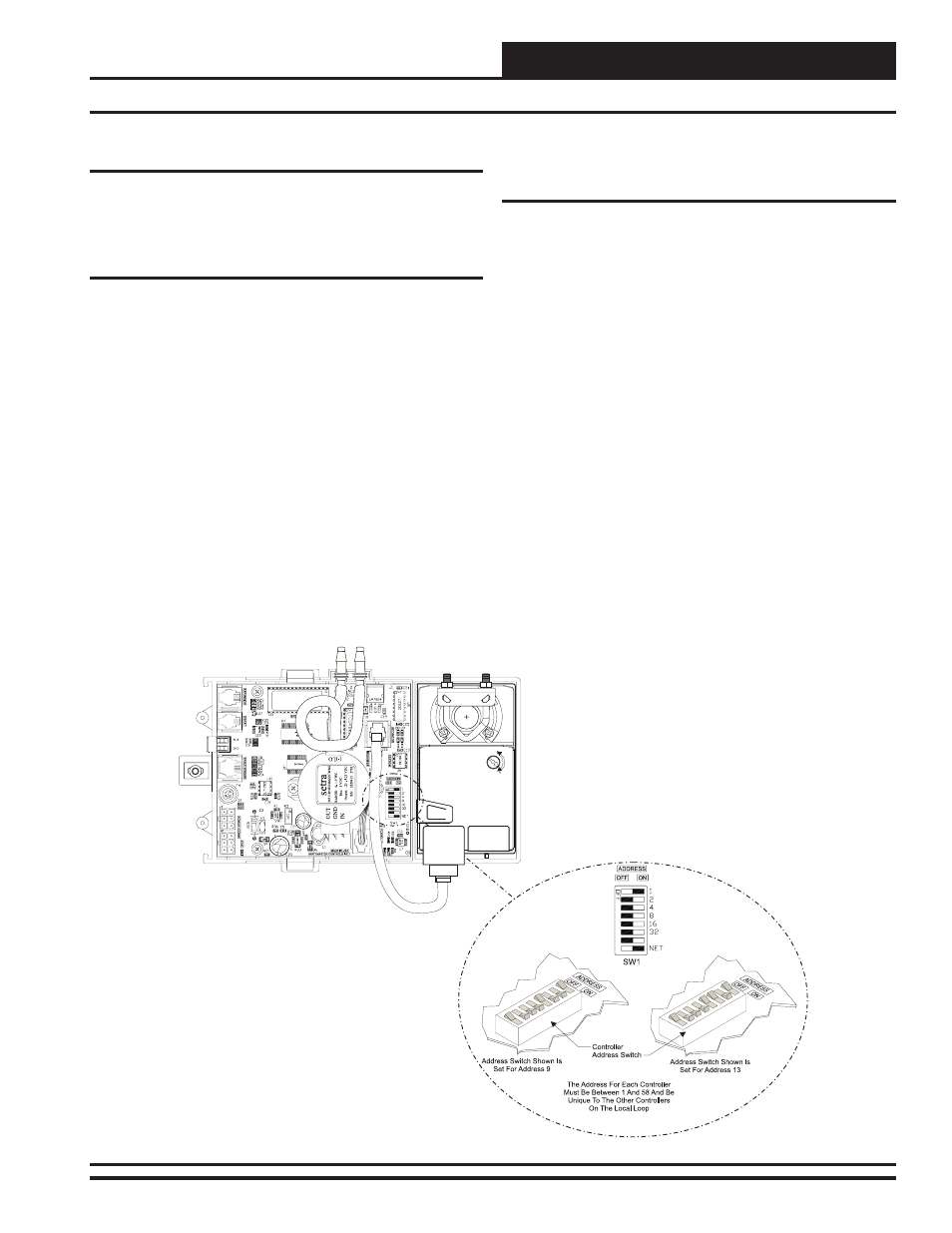
Figure 17: Address Switch Setting
General
In order to have a trouble free start-up, it is important to follow a few
simple procedures. Before applying power for the first time, it is very
important to correctly address the controller and run through a few
simple checks.
Controller Addressing
All Modular VAV/Zone Controller Actuator Packages are equipped
with address switches. If the Modular VAV/Zone Controller Actuator
Package is to operate as a Stand Alone controller (not connected to any
other HVAC unit or VAV/Zone Controller(s)), the controller address
switch should be set for address 1. When the Modular VAV/Zone Con-
troller Actuator Package is to be connected to other Modular VAV/Zone
Controller Actuator Packages on a communication loop, each Modular
VAV/Zone Controller Actuator Package’s address switch must be set
with a unique address between 1 and 58.
When programming the Modular VAV/Zone Controller Actuator Package
on a Stand Alone or Interconnected System and you are asked to enter
the Unit ID, you would enter the address for the controller you wish to
program. When programming the Modular VAV/Zone Controller Actua-
tor Package on a Networked System and you are asked to enter the Unit
ID, you would first enter the MiniLink PD loop address for the loop the
Modular VAV/Zone Controller Actuator Package is connected to and then
enter the Modular VAV/Zone Controller Actuator Package’s address. See
Figure 17 for a diagram depicting address switch settings.
For detailed information regarding communication wiring and connec-
tion for Interconnected and Networked systems, please see the Orion
System Installation & Troubleshooting Guide.
Power Wiring
One of the most important checks to make before powering up the system
for the first time is to confirm proper voltage and transformer sizing for
the Power/Comm board that is connected to it. Each Modular VAV/Zone
Controller Actuator Package requires 6 VA of power delivered to it at 24
VAC. See page 15 of this manual for complete wiring and transformer
sizing information for the VAV/Zone Controller and its associated Power/
Comm board. All VAV/Zone Controllers must be connected to a Power/
Comm board using prefabricated modular cables.
Check all modular connectors to be sure they are completely pushed and
locked into their mating connectors. Confirm that all sensors required
for your system are mounted in the appropriate location and that the
modular cables are plugged into the correct connectors on the Modular
VAV/Zone Controller Actuator Package. Check the actuator cable and
be sure it is plugged in and secured to the modular connector on the
actuator and the Modular VAV/Zone Controller Actuator Package circuit
board modular connector. Check that the Modular Room Sensor modular
connector is connected to one end of the modular sensor cable and the
other end is connected to the modular sensor connector on the Modular
VAV/Zone Controller Actuator Package. Be sure any Expansion Modules
connected to the Modular VAV/Zone Controller Actuator Packages are
also correctly wired per the Expansion Module wiring instructions on
pages 10 through 14 of this manual.
After all the above wiring checks are complete, apply power to the Power/
Comm board that is connected to the Modular VAV/Zone Controller
Actuator Packages.
17
Modular ZCAP Technical Guide
Start-Up & Commissioning