Occupied mode sequences, Sequence of operations, 22 modular zcap technical guide – Orion System Modular VAV/Zone Controller User Manual
Page 22
Space Heating Mode
Occupied Space Heating mode is initiated by the temperature in the space
falling to within 0.5 ºF of the Occupied Heating Setpoint.
If the HVAC unit is in the Supply Air Cooling mode and another VAV/
Zone Controller has a heating demand, the damper/airflow for the VAV/
Zone Controller requiring heating will position itself to provide the
Cooling Minimum amount of air into the space. No modulation open
will occur because the space does not want the cold air currently being
supplied by the air handler.
When the HVAC unit is in the Occupied Supply Air Heating mode, the
damper will be held at the Heating Minimum position until the space
temperature falls to within 0.5 ºF of the Occupied Heating Setpoint.
As the space temperature falls below the heating setpoint, the damper/
airflow calculation causes the air valve to open proportionally until the
maximum setpoint is achieved at 1.5 ºF below the setpoint. This is a 2
ºF proportional window starting 0.5 ºF above the heating setpoint to 1.5
ºF below the heating setpoint.
Two different configurations are available for the Occupied Space Heat-
ing mode. If the box is configured to allow reheat during Supply Air
Heating mode, the reheat relays can be activated even when the HVAC
unit is in the Supply Air Heating mode. If the box is configured not to
allow reheat when the HVAC unit is in Supply Air Heating mode, the
box heat relays will be de-energized when the HVAC unit is in Supply
Air Heating mode. In either configuration, when the HVAC unit is in
the Supply Air Heating mode, the damper will modulate open propor-
tionally to the space demand. The proportional window for the space
temperature is to 1.5 ºF below the heating setpoint. This allows the space
to take advantage of the warm supply air in the duct.
The VAV/Zone Controller can activate auxiliary heating relays if the
Expansion Module has been connected and the correct number of heat-
ing stages (1, 2 or 3) has been configured. During demands for heat, the
first stage will activate whenever the space temperature drops below the
heating setpoint. The second stage will activate if the space temperature
falls 1.0 ºF below the heating setpoint. The third stage will activate if
the space temperature falls 2.0 ºF below the heating setpoint. There is a
two-minute delay between staging. This prevents stages from activating
at the same time. Once a heating stage has been activated, it must remain
on for at least one minute. Once it has been deactivated, it must remain
off for at least two minutes. The third stage relay will deactivate when
the space temperature rises to within 1.0 ºF of the heating setpoint. The
second stage relay will deactivate when the space temperature rises to
the heating setpoint. The first stage relay will deactivate when the space
temperature rises above the heating setpoint by 1.0 ºF. See Table 2 for a
complete layout of the various fan & heat relay staging points.
Modulating (Proportional) Heat
The Modular VAV/Zone Controller Actuator Package also provides an
analog output for control of a modulating hot water valve or SCR elec-
tric heater. It provides a 0-10 VDC signal to control the heating device.
When the space temperature drops to 0.5 ºF above the Heating Setpoint
the output starts at 0 VDC and ramps up to 10 VDC at 1.5 below the
Heating Setpoint.
Auxiliary Heat
The Auxiliary Heat option allows for a separate setpoint that is different
from the other heating setpoints. The Auxiliary Heat Relay energizes at
0.5 ºF below the Auxiliary Heat Setpoint and de-energizes 0.5 ºF above
the Auxiliary Heat Setpoint. The Auxiliary Heat will continue to func-
tion regardless of the HVAC Mode the VCM-X is in or at any airflow
condition. This is typically used to control baseboard heat or an external
duct heater. See Table 2 for a complete layout of the various fan and
heat relay staging points.
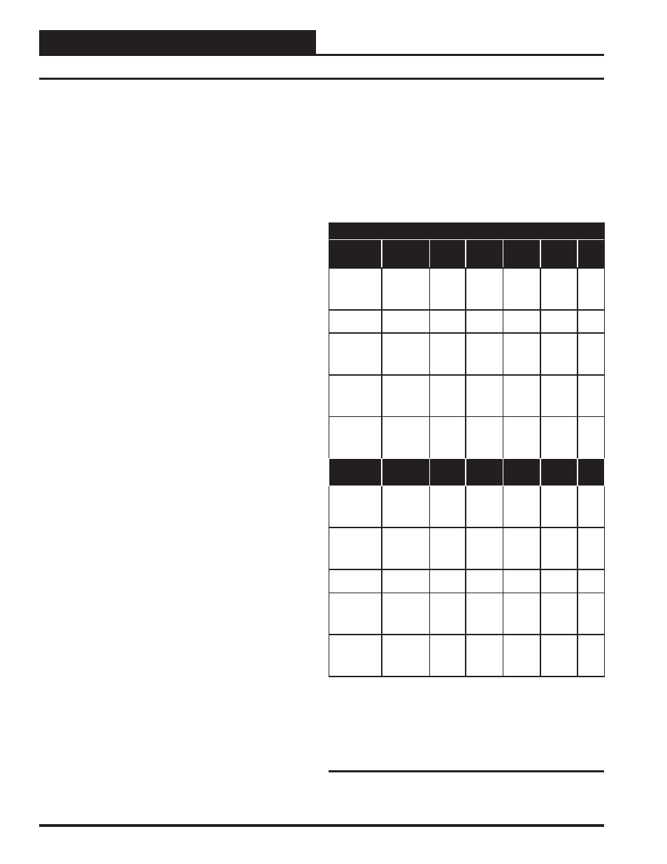
Fan & Reheat Relay Staging
Relays
Stage On At
Series
Fan
Parallel
Fan
Heat
Stage 1
Heat
Stage 2
Heat
Stage 3
Aux.
Heat
0.5 ºF
Above
Box Heat
Setpoint
ON With
HVAC Fan
*See
Note 1
X
At Box Heat
Setpoint
X
1.0 ºF
Below Box
Heat
Setpoint
X
2.0 ºF
Below Box
Heat
Setpoint
X
0.5 ºF
Below Box
Heat
Setpoint
X
Relays
Stage Off At
Series
Fan
Parallel
Fan
Heat
Stage 1
Heat
Stage
2
Heat
Stage 3
Aux.
Heat
1.0 ºF
Above
Box Heat
Setpoint
OFF With
HVAC Fan
See Note 1
X
See
Note 2
1.0 ºF
Above
Box Heat
Setpoint
X
At Box Heat
Setpoint
X
1.0 ºF
Below
Box Heat
Setpoint
X
0.5 ºF
Above
Aux. Heat
Setpoint
X
Note:
1.) If check for main fan status is selected when configuring the controller, the
series fan will energize anytime the HVAC unit’s fan is operating, even in the
unoccupied mode.
2.) The parallel fan will continue to run for 2 minutes following the relay stag-
ing off.
Table 2: Fan & Reheat Relay Staging
Occupied Mode Sequences
22
Modular ZCAP Technical Guide
Sequence of Operations