Inputs and outputs, Vav/zone controller analog inputs, Other controller connections – Orion System Modular VAV/Zone Controller User Manual
Page 8: Oe325-01 zone controller expansion module, Overview, 8modular zcap technical guide
The following inputs and outputs are available on the VAV/Zone
Controller and the OE325-01 Zone Controller Expansion Module. For
component locations of the inputs on the VAV/Zone Controller and VAV
Zone Controller Expansion Module see Figures 3, 4, and 6. For wiring
of inputs and outputs, see Figures 7 through 13.
VAV/Zone Controller Analog Inputs
Space Temperature
The Modular Room Sensor that reads space temperature is attached
to this input. The Modular Sensor connects via a modular cable to the
Modular VAV/Zone Controller Actuator Package.
Airflow Sensor
If the OE744-31-VAVZ Modular VAV/Zone Controller Actuator Package
is being used, the terminal unit’s pressure pick-up tube must be con-
nected with FRP tubing to the barb fittings on the side of the enclosure.
This pressure sensor input is used for CFM (airflow) calculations. If an
Airflow Sensor is attached to this input, the VAV/Zone Controller will
automatically detect this and switch to pressure independent operation.
If the sensor is not attached or becomes defective, the controller auto-
matically reverts to pressure dependent operation.
Supply Air Temperature Sensor
A Supply Air Temperature Sensor can be connected to these terminals. It
should be mounted in the supply duct close to the terminal unit where the
VAV/Zone Controller is installed. This sensor can be used for monitor-
ing purposes or in place of the Supply Air Temperature Broadcast from
the VCM-X Controller.
Other Controller Connections
Expansion Board Modular Connector
This modular connector is used to connect the optional OE325-01 Zone
Controller Expansion Module to the Modular VAV/Zone Controller
Actuator Package. This module is only required when electric or hot
water heating and/or fan terminal control is required. The Expansion
Module is not required for cooling only terminal units.
Actuator Modular Connector
This modular connector is used to connect a modular cable from the
VAV/Zone Controller to a tri-state actuator.
Power/Comm Modular Connectors
These two modular connectors, (labeled P1 & P2), are used to connect
modular cables from the Power/Comm board that supplies 24 Volt power
and communications to the controller and to supply 24 Volt power and
communications from each VAV/Zone Controller Package on the local
loop to the next one on the local loop.
Modular Service Tool DIN Connector
This connector is used to connect a cable between the Modular Service
Tool or the USB-Link and the Modular VAV/Zone Controller Actuator
Package for programing and configuration of the VAV/Zone Controller.
OE325-01 Zone Controller Expansion
Module
As previously stated, when control of a fan or if heating is required, the
OE325-01 Zone Controller Expansion Module is required.
Relay Output #1 - Fan Enable
The first expansion relay on the Output Expansion boards is used for
energizing the fan on Series or Parallel Fan Terminal Units.
Relay Output #2 - Heating Stage 1
If you have at least one stage of heating, this is the relay used to energize
the 1st stage of terminal unit heating. This heating stage can either be
used with electric heat or On/Off hot water valve control.
Relay Output #3 - Heating Stage 2
If you have two stages of electric heating, this relay controls the 2nd
stage of electric heat. For 3 stage heating, this relay output would be
energized for both the 2nd and 3rd stage of heat. See the following
paragraph for more information regarding 3 stage heating applications.
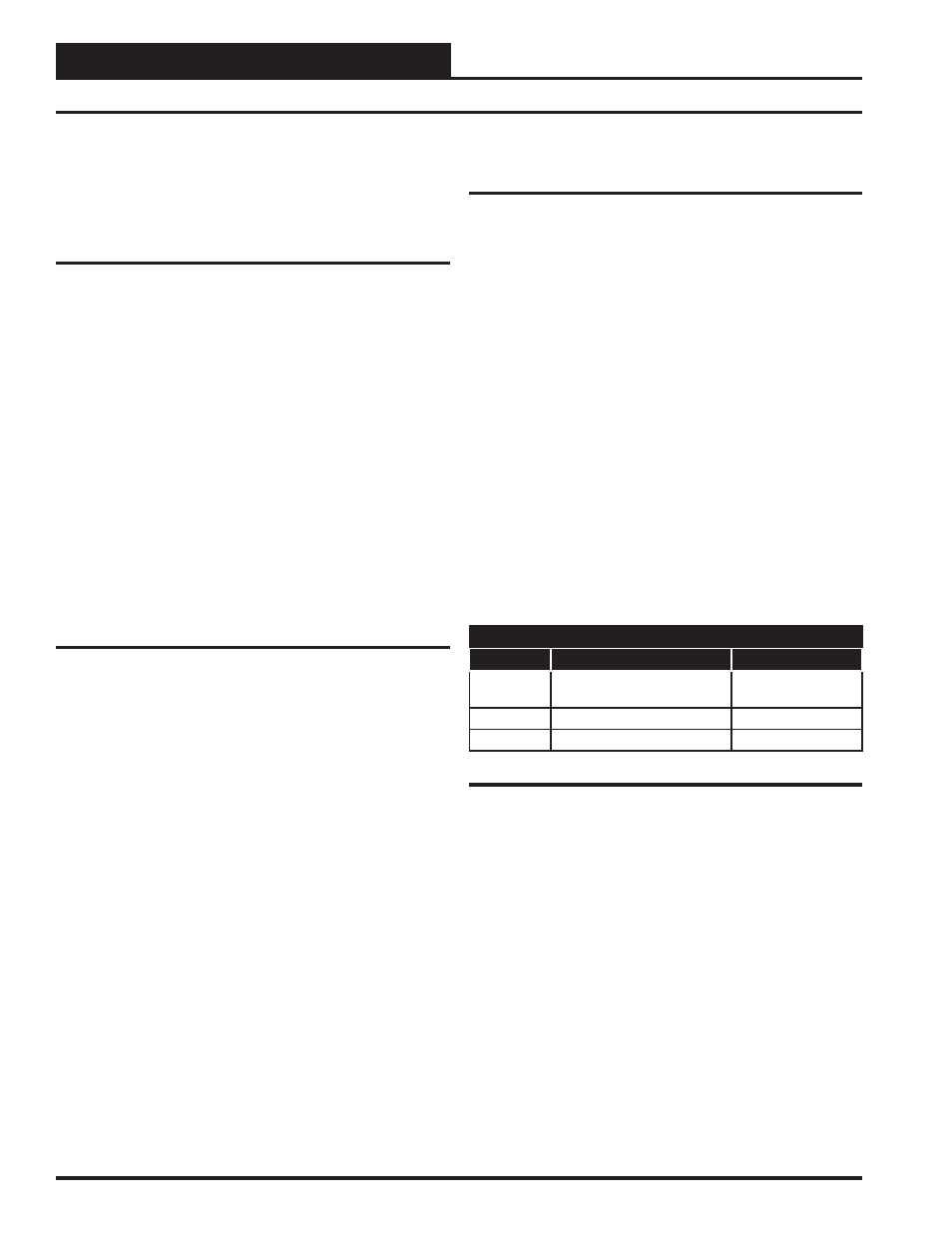
3 Stage Heating Applications
If three stages of electric heat are configured, relays #2 and #3 will stage
in a staggered sequence. This allows you to achieve 3 stages of heating
using only relays #2 and #3. Each of the 3 heating elements should be
sized for one third of the total KW output required. Both the 2nd and 3rd
stage heating contactors (C2 & C3) must be connected to Relay Output
#3. See Table 1 below for relay sequencing information.
Relay Staging
Stage No.
Relay Output #2
Relay Output #3
1
VAV/Zone Controller
Package ON (C1)
OFF (C2 & C3)
2
OFF (C1)
ON (C2 & C3)
3
ON (C1)
ON (C2 & C3)
Table 1: Relay Sequencing For 3 Stage Heating
Auxiliary Heat Relay
If you have an auxiliary heat source you would like to control in addition
to or in lieu of the other heat options, you can connect it to relay R4 on
the expansion module. This relay has a separate setpoint available for
controlling an electric baseboard or duct heater or a two position hot
water valve for a baseboard radiator or duct heater.
Analog Output
If you are using hot water or steam heating via a modulating steam
or hot water valve, this output can supply a 0-10 Volts DC signal for
proportional control of the valve.
Inputs and Outputs
8
Modular ZCAP Technical Guide
Overview