Lcd display screens, Status & alarm screens, Mhgrv-x field technical guide – Orion System MHGRV-X User Manual
Page 11: Status screens, Alarm screens
MHGRV-X Field Technical Guide
LCD DISPLAY SCREENS
11
Status & Alarm Screens
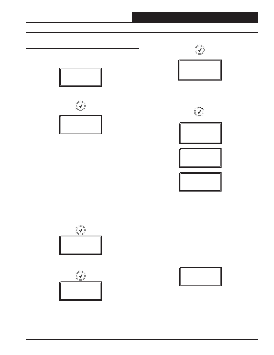
Status Screens
Refer to the following map when navigating through the Status
Screens. From the STATUS Screen, press
<ENTER>
to scroll
through the screens.
STATUS
MODE
OFF,REHEAT,
FLUSH,AUX,FORCE!
VLV POS
100%
SA TEMP
XX.X
ACTIV SP
XX.X
OR INACTIVE
Alarm Screens
Refer to the following map when viewing Alarm Screens. These
screens will display automatically when alarms are present. For
more information, see pages 13 & 14.
SUPPLY AIR TEMPERATURE
40ºF to 150ºF or 5ºC to 65ºC.
If no sensor is detected, screen will display “NO SENSR”
ALARMS
Status Screens shown below will scroll automatically if LCD display is
left on this screen for 20 seconds.
MODE
This screen displays the current mode of operation of the MHGRV-X
Controller. The mode options are:
OFF:
This mode will display if the unit is not in Dehumidifi cation Mode
and there is no call for Modulating Hot Gas Reheat (MHGR).
REHEAT:
During Dehumidifi cation, the unit will enter the Reheat Mode
and will begin to modulate the MHGR Valve to maintain the Supply Air
Temperature Setpoint. The unit will leave the Reheat Mode when the unit
leaves the Dehumidifi cation Mode.
FLUSH:
This mode will display if the unit is performing a cooling fl ush
cycle or a reheat fl ush cycle (see Additional Features, page 8).
AUX:
If Aux operation has been enabled, a 0-10 VDC signal can be
used to proportionally modulate the MHGR Valve between 0 – 100 %.
FORCE!:
The unit is in the Force Mode.
VALVE POSITION
0 to 100 percent
ACTIVE SUPPLY AIR SETPOINT
Calculated from SAT setpoint and reset signal. Displays INACTIVE
when in OFF Mode or not needing to be calculated.
The alarms are as follows:
NO ALARMS:
This will be shown if there are no current alarms.
SAT FAIL ERROR:
The Supply Air Temperature sensor has been dis-
connected for more than 60 seconds. This alarm will be disabled when
the sensor is reconnected.
COMM T/O ERROR:
Communications have been lost with the main
controller. This alarm will disable when communications resume.
FLUSHTMR
COOLING,HEATING,
DISABLED
FLUSH TIMER AND FLUSH STATUS
Flush Timer screen will display if the unit is in Cooling Flush Mode, Heat-
ing Flush Mode, or Disabled. It will then display the time remaining in
minutes until the Flush Cycle begins. If the unit is in the Flush Cycle, it
will display FLUSH CYCLE ON.
FLUSHTMR
XX
FLUSH
CYCLE ON