Wiring, Mhgrv-x to aaon unit controller wiring, Mhgrv-x field technical guide – Orion System MHGRV-X User Manual
Page 5: Communications wiring, C cable connecting to the appropriate i
MHGRV-X Field Technical Guide
WIRING
5
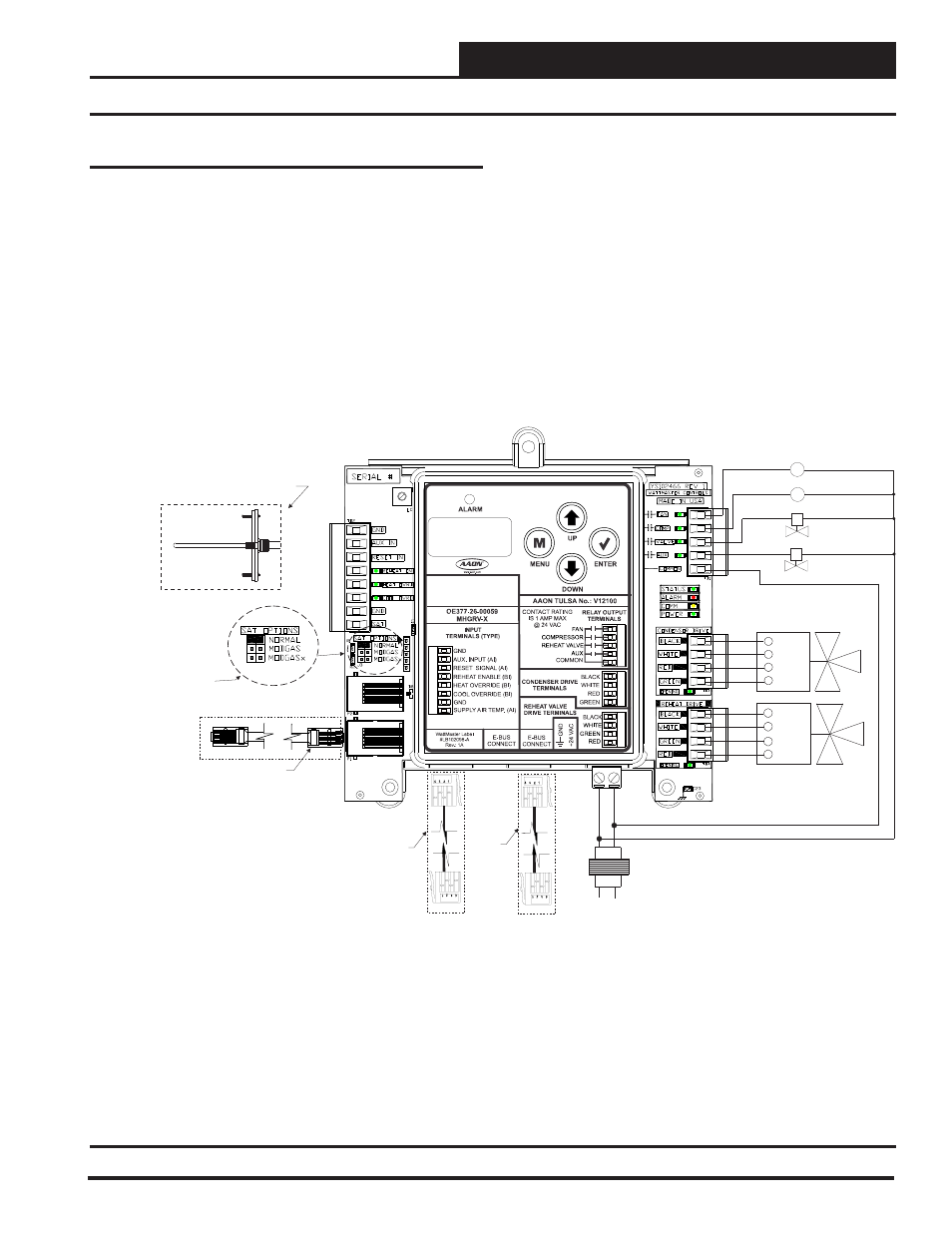
Figure 2: MHGRV-X Controller to AAON Unit Controller Wiring
MHGRV-X to AAON Unit Controller Wiring
Line
GND
24V
AC
40 VA
Transformer
Minimum
Supply
Air Temperature
Sensor
Mount In Supply
Air Duct
RED
GRN
WHT
BLK
Condenser Valve #1
HGR Valve #1
RED
GRN
WHT
BLK
EBC E-BUS Cable
Connects To
VCB-X Expansion
Port When Used
With VCB-X
Controller
MHGRV-X CONTROLLER
(OE377-26-00059)
Fan
Compressor
HGR Solenoid Valve
2 Position HGR Valve (Optional)
C1
C2
COMM
I C Cable
Connects To
Port On
Any Non VCB-X Controller Or
Expansion Module
2
I C
2
Connect
o AI2 & GND
On Main Controller
(This Does Not Apply To
CAV/VAV Or MUA Applications)
Supply Air Temperature
Sensor T
See
For
Settings.
Only One Supply Air
Temperature Sensor Can Be
Used Per Application.
Table 9 On Page 18
SAT OPTIONS
Jumper
EBC
E-BUS
Cable
Connects
To Reheat
Expansion
Module
Communications Wiring
For connection to a VCB-X Controller, VCB-X Expansion Module,
and Reheat Expansion Module, use an E-BUS Cable to connect to
the appropriate E-BUS port on those modules and/or controller.
For all other controllers, including the VAV/CAV, MUA,VCM,
VCM-X, SA, and RNE Controllers, use an I
2
C Cable connecting to
the appropriate I
2
C ports on those controllers.
When connected to an AAON Unit Controller, the Supply Air
Temperature Sensor is attached to the Main Controller. See Figure
2 below.
See the SAT Wiring Conditions Table and SAT OPTIONS jumper
settings in Tables 7 & 9, page 18.