Pm (phase modulation) – OWON AG-S series User Manual
Page 28
5.Front Panel Operation
Note:
The Sum of the Deviation and the Carrier Frequency should be equal to or less than
maximum frequency of the selected function plus 1kHz.
For an External Source, the Deviation is controlled by the voltage Level of the signal
connected to the Modulation In connector in the rear panel. +5V corresponds to the
selected Deviation and -5V to the negative selected Deviation.
PM (Phase Modulation)
The modulated waveform consists of two parts: the Carrier Waveform and the
Modulating Waveform. The Carrier Waveform can only be Sine. In PM, the phase of the
Carrier Waveform varies with the instantaneous voltage level of the modulating
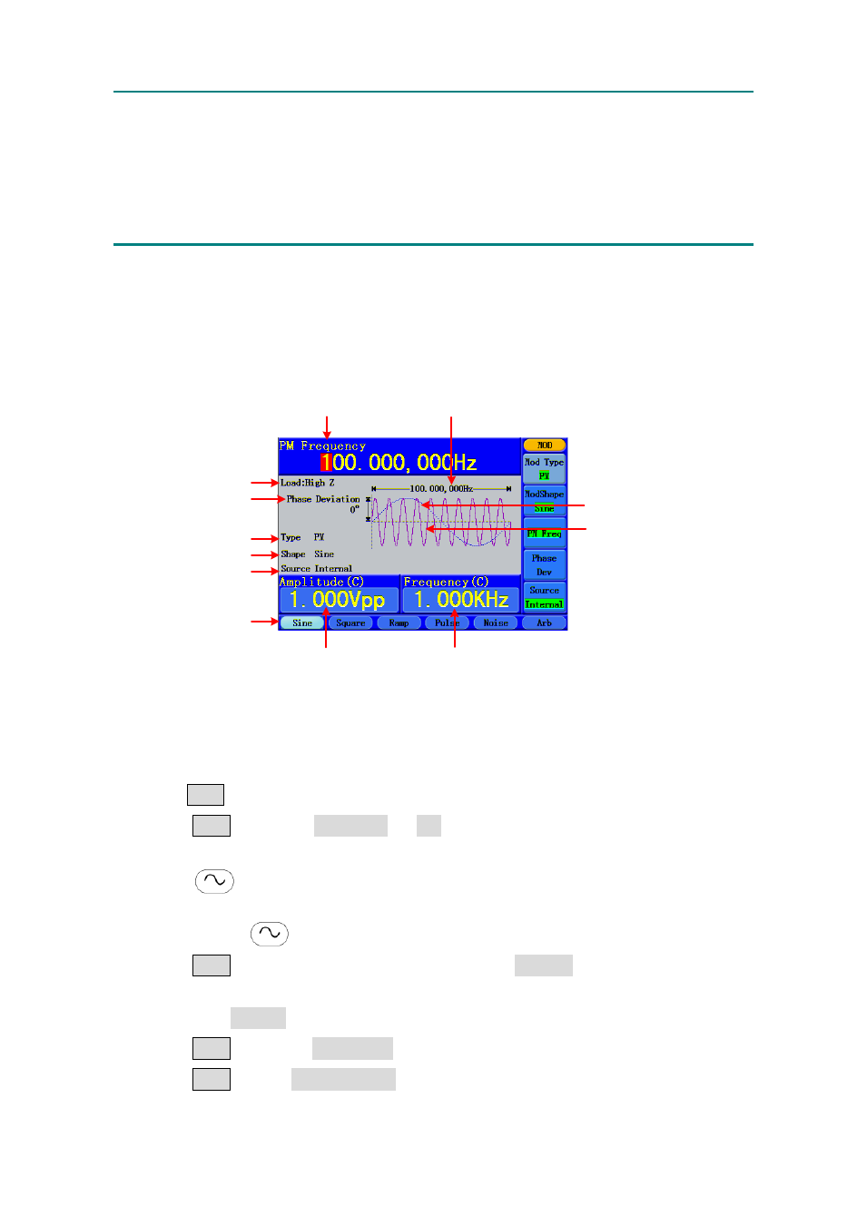
waveform. The user interface of the PM is shown as below.
Current Parameter
Carrier
Frequency
Carrier
Amplitude
Carrier Waveform
Carrier Waveform
Modulating Waveform
Load
Phase Deviation
PM Frequency
Mod Type
Mod Shape
Source
Figure 5-14: The User Interface of PM
How to set the parameters of PM
(1)
Press Mod function button to enter the Modulation mode.
(2)
Press F1 to switch Mod Type to PM. If the Carrier Waveform is not Sine, the
system will switch it to Sine automatically.
(3)
Press
button to display the waveform and parameters of the Carrier
Waveform. You can change the parameters, please refer to "To Output Sine Signals"
on P11. Press
button again to return to the Modulation mode interface.
(4)
Press F5 to select the source. If the source is External, use the Modulation In
connector in the rear panel to input the external signal, then skip ahead to step (6). If
you choose Internal, continue to the steps below.
(5)
Press F2 to choose Mod Shape, you can choose Sine, Square or Ramp.
(6)
Press F3 to set PM Frequency. The range is 2 mHz~20 KHz (Internal source
only).
23