1 important notes prior to installation, 2 wall openings, 3 installation materials – REMKO RVT 263 DC User Manual
Page 27: 4 installation indoor unit, 5installation instructions for qualified personnel
5
Installation instructions for qualified personnel
5.1 Important notes prior to instal-
lation
n
Transport the unit in its original packaging as
close as possible to the installation location.
You avoid transport damage by doing so.
n
Check the contents of the packaging for com-
pleteness and check the unit for visible trans-
port damage. Report any damage immediately
to your contractual partner and the shipping
company.
n
Lift the unit on the corners and not on the
refrigerant or condensate drainage connec-
tions.
n
The refrigerant piping (liquid and suction pipe),
valves and connections must be insulated to
make them vapour diffusion proof. If necessary
also insulate the condensate drainage line.
n
Select an installation location which allows air
to freely flow through the air inlet and outlet
(see section "Minimum clearances")
n
Do not install the unit in the immediate vicinity
of devices which generate intensive thermal
radiation. Installation in the vicinity of thermal
radiation reduces the unit output.
n
Only open the shut-off valves on the refrigerant
piping after installation is complete.
n
Seal off open refrigerant piping with suitable
caps or adhesive strips to prevent the infiltra-
tion of moisture and never kink or compress
the refrigerant piping.
n
Avoid unnecessary bends. This minimises the
pressure loss in the refrigerant piping and
ensures that the compressor oil can flow back
without obstruction.
n
Make special preparations regarding the oil
return if the outdoor unit is located above the
indoor unit (see section "Oil return measures").
n
Add refrigerant if the basic length of the refrig-
erant piping exceeds 5 metres. For the quantity
of additional refrigerant, refer to chapter
"Adding refrigerant".
n
Perform all electrical wiring in accordance with
applicable DIN and VDE standards.
n
Ensure the electrical cables are properly con-
nected to the terminals, otherwise there is a
risk of fire.
n
Only use the fasteners contained in the scope
of delivery with the units.
n
Use four supports and the associated hooks to
attach the ceiling cassette (only applies to
ceiling cassettes).
n
Use the insulated condensate hose in the
scope of delivery as a junction piece to the
continuing condensate drain. Secure the con-
densate drain with the supplied clamps.
5.2 Wall openings
n
A wall opening of at least 70mm diameter and
10mm incline from the inside to the outside
must be created.
n
To prevent damage to the lines, the interior of
the wall opening should be padded or, for
example, lined with PVC pipe (see figure).
n
After installation has been completed, use a
suitable sealing compound to close off the wall
opening, taking account of fire protection regu-
lations (responsibility of customer). Do not use
cement or lime containing substances!
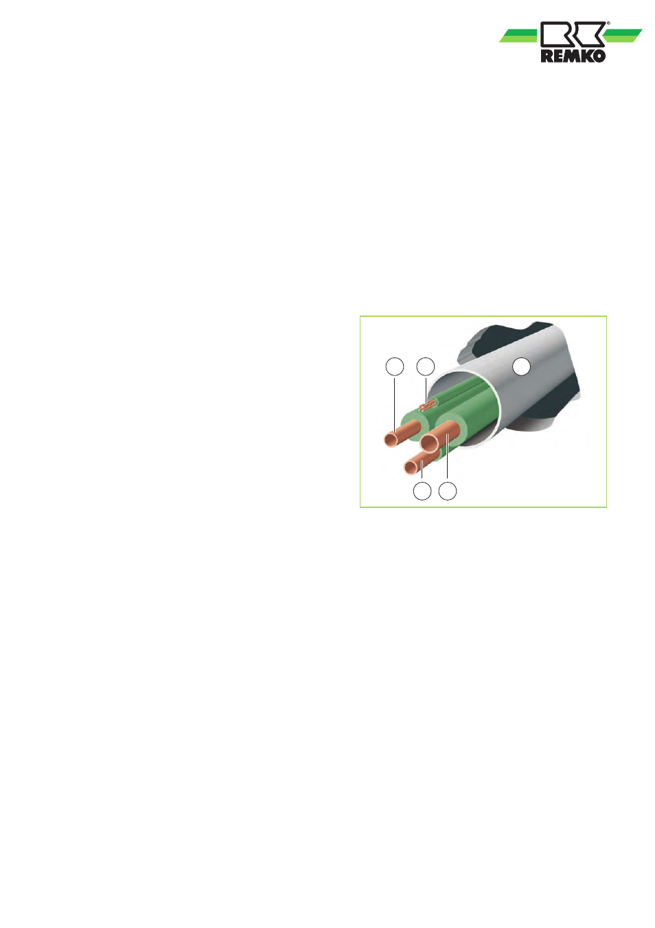
2
1
5
3
4
Fig. 30: Wall opening
1: Liquid line
2: Control line
3: Condensate drainage line
4: Suction pipe
5: PVC pipe
5.3 Installation materials
The indoor unit is attached to the wall by a wall
bracket and 4 screws (to be provided by the cus-
tomer).
The outdoor unit is attached by 4 screws and a
wall bracket to the wall or fixed by a floor bracket to
the ground.
5.4 Installation indoor unit
The indoor unit is designed for horizontal wall
installation above doors. However, it can also be
used in the upper wall area (min. 1.75m above the
floor).
27