Remko rvt...dc – REMKO RVT 263 DC User Manual
Page 34
The following instructions describe the installation
of the cooling cycle and the assembly of the indoor
unit and the outdoor unit.
1.
The required pipe diameters are given in the
table "Technical data".
2.
Install the indoor unit and connect the refrig-
erant piping as described in the operating
manual for the indoor unit.
3.
Use the wall or floor brackets to fit the out-
door unit against structural parts approved to
support the static load (refer to the installa-
tion instructions for the brackets).
4.
Ensure that structure-borne sound is not
transferred to parts of the building. Use vibra-
tion dampers to reduce the effects of struc-
ture-borne sound!
5.
Lay the refrigerant piping from the indoor unit
to the outdoor unit. Ensure that the fasten-
ings are adequate and if necessary, take
appropriate oil return measures!
6.
Remove the factory-fitted protective caps and
union nuts on the connections. These should
be used later in the installation process.
7.
Before flanging the refrigerant piping, ensure
that the union nut is fitted on the pipe.
8.
Prepare the laid refrigerant pipings as shown
9.
Verify that the shape of the flange is correct
10.
First connect and hand-tighten the refrigerant
piping to ensure it is correctly seated.
11.
Then tighten the fittings with 2 appropriately-
sized open-ended spanners. Use one
spanner to counter the force when tightening
12.
Use insulation hoses which are designed for
this temperature range and are diffusion
proof.
13.
Observe the permitted bending radius for the
refrigerant piping during installation. Never
bend a pipe twice in the same place. Brittle-
ness and cracking can result.
14.
Apply appropriate heat insulation to the
installed refrigerant piping, including con-
nector.
15.
Take the same action at the shut-off valves
for all subsequent refrigerant piping.
Label the refrigerant piping (injection and suc-
tion pipes) as well as the associated electrical
control lines of each interior unit with a letter.
Only connect the lines to their associated con-
nections.
NOTICE!
Always pay attention to the affiliation of the
electrical lines and refrigerant piping! The con-
nections of the individual circuits must not be
mixed up. Mixing up the assignment of control
lines and refrigerant piping can have fatal con-
sequences (compressor damage)!
Commissioning of the individual circuits must
be carried out successively.
2
1
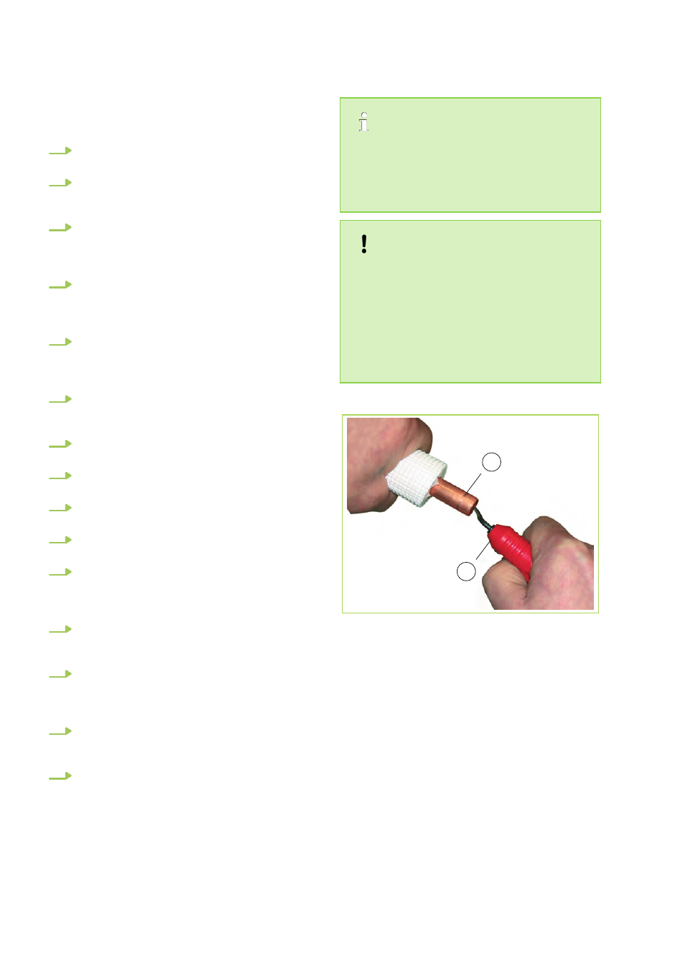
Fig. 39: Deburring the refrigerant piping
1: Refrigerant piping
2: Deburrer
REMKO RVT...DC
34