Installation – REMKO RM Series User Manual
Page 19
C
onnection options
1 Exit on wall, right
2 Exit through wall, right
3 Exit through wall, left
4 Exit on wall, left
1
2
3
4
Connection options for
indoor unit
The units are factory filled with
dry nitrogen to check for leaks.
The pressurised nitrogen is
released when loosening the
union nuts.
CAUTION
Installing the unit
The indoor unit is fastened by
means of wall bracket. Take into
account the air outlet underneath
the unit.
1. Use the wall bracket dimensions
to mark the fixing points on
structural parts approved to
support the static load.
2. If necessary, remove the break-
outs on the housing.
3. Connect the refrigerant
pipes, electrical cables and
condensation pipe to the indoor
unit as described below.
4. Tilt back the indoor unit and
hang it into the wall bracket.
Press the underside of the unit
into the bracket (Fig 6).
5. Check that the unit is level.
Wall bracket
for indoor unit
Attach the wall bracket for the
unit using suitable screws and wall
plugs.
Installation
Installation should only be
performed by authorised
specialists.
NOTE
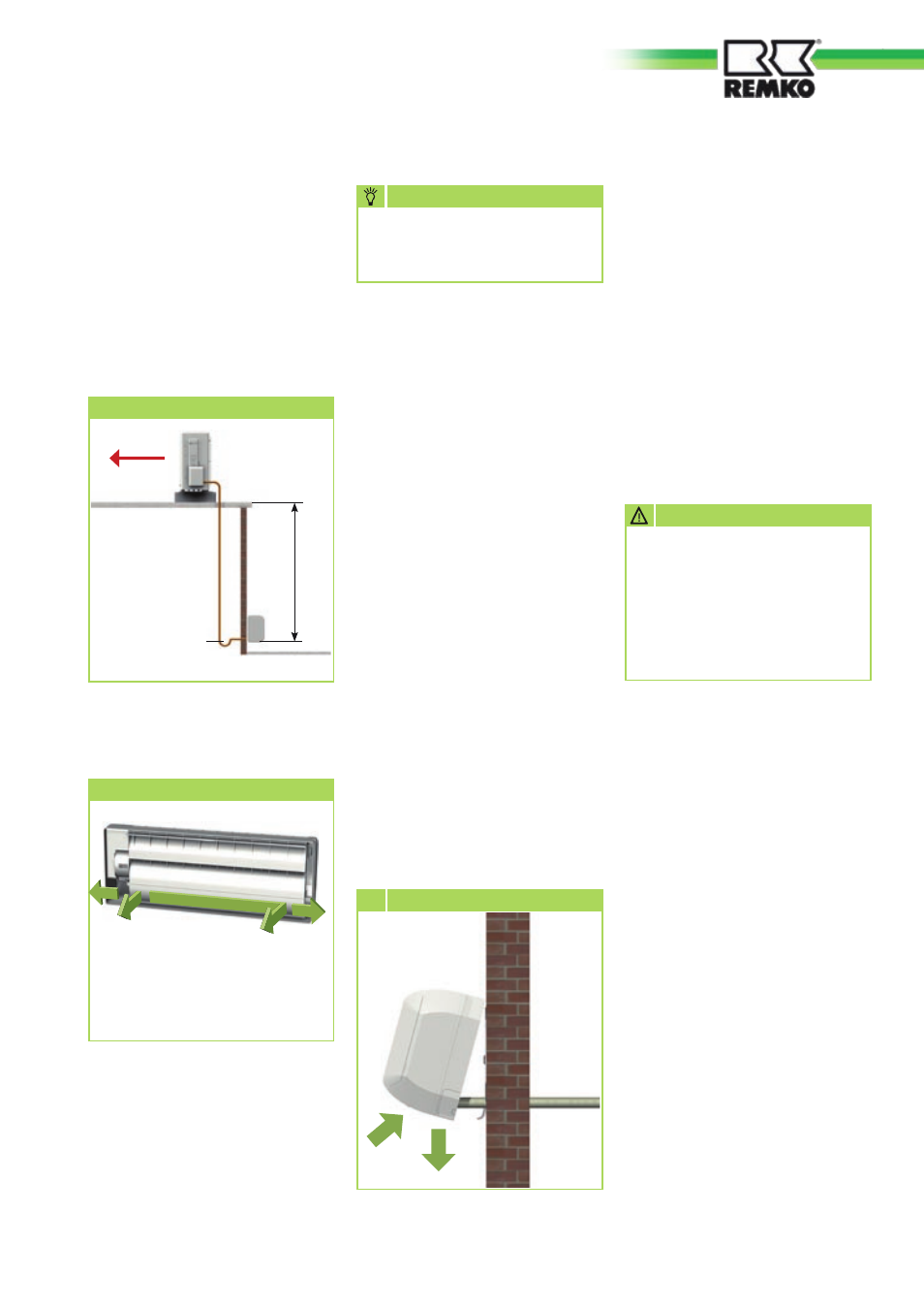
Oil return measures
If the outdoor component is
installed at a higher level than
the indoor unit, suitable oil return
measures must be taken. Usually
an oil pump bend is installed
for every 2.5 metres of height
difference.
6
Hooking in
Connecting the refrigerant
pipes
The connections to the refrigerant
pipes are made at the rear of the
unit (responsibility of customer).
It may be necessary to fit a reducer
or flared adapter to the indoor
unit. These fittings are included
as standard. Once installed, the
connections should be made tight
against vapour diffusion.
The procedures for installing the
refrigerant circuit and mounting
the indoor unit and outdoor
component are described below.
1. The required pipe diameters are
given in the table "Technical
data".
2. Remove the factory-fitted
protective caps and union
nuts on the connections.
These should be used during
installation.
3. Before flanging the refrigerant
pipes, ensure that the union nut
is fitted on the pipe.
4. Prepare the laid refrigerant
pipes as shown below
(page 20, figs 7+8).
Oil return measures
Outdoor unit
Oil pump bend
in suction pipe
to outdoor
component one
every 2.5 metres of
rising pipe
Radius:
min. 50 mm
max. 15 m
Indoor unit
19