Electrical connection diagram – REMKO RM Series User Manual
Page 23
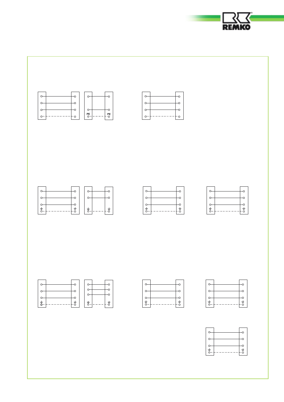
Electrical connection diagram
RM 326 / RM 335
Indoor unit
Circuit B
Outdoor
component
Circuit B
Indoor unit
Circuit C
Outdoor
component
Circuit C
Indoor unit
Circuit A
Neutral conductor
Phase conductor
Earth conductor
230 V, 1~,
50 Hz,
L1 / N / PE
Control conductor
Outdoor
component
Circuit A
Compressor
N
1
N
L
L
N
L
N
L1
Neutral conductor
Phase conductor
Earth conductor
Control conductor
Compressor
N
1
N
L
L
Neutral conductor
Phase conductor
Earth conductor
Control conductor
Compressor
N
1
N
L
L
Mains cable
3
3
3
RM 226 / RM 235 / RM 252 / RM 268
Indoor unit
Circuit A
Mains cable
Neutral conductor
Phase conductor
Earth conductor
230 V, 1~,
50 Hz,
L1 / N / PE
Control conductor
Outdoor
component
Circuit A
Compressor
Indoor unit
Circuit B
Outdoor
component
Circuit B
PE
PE
N
1
N
L
L
N
L
N
L1
Neutral conductor
Phase conductor
Earth conductor
Control conductor
Compressor
PE
PE
N
1
N
L
L
3
3
RM 426 / RM 435
Indoor unit
Circuit A
Mains cable
Outdoor
component
Circuit A
Indoor unit
Circuit B
Outdoor
component
Circuit B
Indoor unit
Circuit C
Outdoor
component
Circuit C
230 V, 2~,
50 Hz,
L1 / L2 / N / PE
Neutral conductor
Phase conductor
Earth conductor
Control conductor
Compressor
N
3
1
N
L
L
N
L
L
N
L1
L2
Neutral conductor
Phase conductor
Earth conductor
Control conductor
Compressor
N
1
N
L
L
Neutral conductor
Phase conductor
Earth conductor
Control conductor
Compressor
N
1
N
L
L
3
3
Indoor unit
Circuit D
Outdoor
component
Circuit D
Neutral conductor
Phase conductor
Earth conductor
Control conductor
Compressor
N
1
N
L
L
3
23