Transportation and packaging, Description of the equipment – REMKO RM Series User Manual
Page 5
The equipment was shipped in
sturdy packaging. Immediately
check the equipment on delivery
and make a note of any damage or
missing parts on the delivery note.
Inform the forwarding agent and
contractual partner.
Warranty claims at a later date will
not be accepted .
Transportation and
packaging
RM
226 IT
RM
235 IT
RM
252 IT
RM
268 IT
RM
326 IT
2,6
RM
326 IT
3,6
RM
335 IT
RM
426 IT
RM
435 IT
RM 226 AT
••
RM 235 AT
••
RM 252 AT
••
RM 268 AT
••
RM 326 AT
••
•
1)
RM 335 AT
•••
RM 426 AT
••••
RM 435 AT
••••
Scope of supply
1) 2 RM 326 IT indoor units and 1 RM 326 IT indoor unit with 2.6 kW and 3.5 kW cooling output
respectively
5
Description of the
equipment
The RM 228-435 air conditioning
equipment consists of an REMKO
RM...AT outdoor component and
two, three or four RM...IT interior
units.
The outdoor component serves to
output the heat extracted by the
interior unit
from the room being cooled.
The outdoor component can be
installed outdoors or indoors. The
latter requires the fulfilment of
certain conditions. The indoor unit
is designed for interior use and
should be mounted high up on
a wall. It is operated by infrared
remote control.
The outdoor component consists
of two (circuits A,B), three (circuits
A,B,C) or four (circuits A,B,C,D)
refrigerant circuits, each of which
is equipped with a compressor,
finned vaporiser, flow regulator
and one or two liquefier fans.
Each refrigerant circuit in the
outdoor component is controlled
by the regulators in the indoor
units.
The indoor unit comprises a finned
vaporiser, vaporiser fan, controller
and condensation tray.
Winter controllers, floor and wall
brackets, refrigerant pipes and
condensation pumps are also
available as accessories.
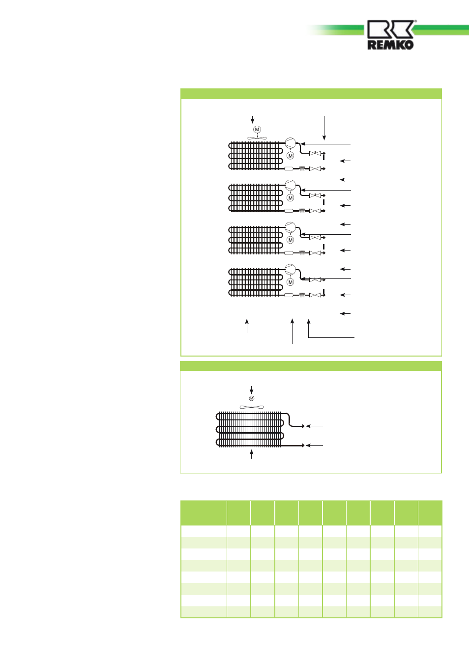
Schematic of refrigerant circuit in indoor unit
Vaporiser fan
Vaporiser
Connection to suction pipe
Connection to injection pipe
Connection for pressure gauge
Schematic of exterior refrigerant circuit
Compressor A
Connection valve
Suction pipe A
Connection valve
Injection pipe A
Compressor B
Connection valve
Suction pipe B
Connection valve
Injection pipe B
Compressor C
Connection valve
Suction pipe C
Connection valve
Injection pipe C
Compressor D
Connection valve
Suction pipe D
Connection valve
Injection pipe D
Liquefier fan
Liquefier 1-4
Filter dryer 1-4
Flow regulator
Capillary tube 1-4