REMKO SuperTec-Monitor User Manual
Page 7
DIP switch SW 2
during normal operation
■
Switch off the power supply of
the outdoor unit.
■
To do so, set switches 1-6 of
SW2 to their initial setting. All
switches in the OFF position
ON
1 2 3 4 5 6
■
Place the system back into serv-
ice using the heat pump manager.
The initial setting of DIP switch
SW2 in normal operation looks like
this:
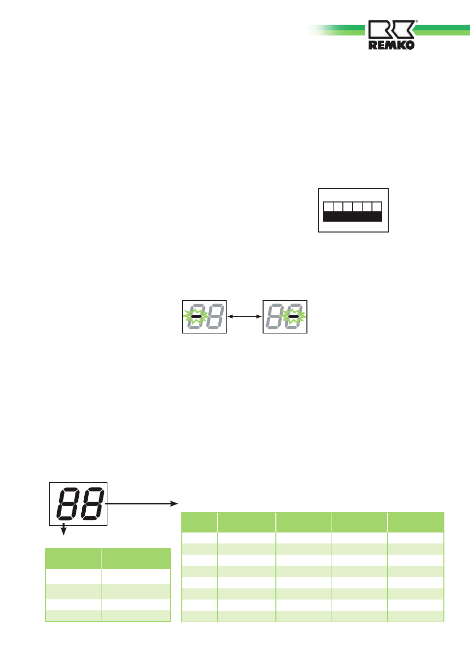
Seven-segment LED display
When the power supply is
switched on , the LEDs flash while
the air conditioning system is car-
rying out an internal system check.
This lasts max. 4 minutes.
Interval:
1 second
LEDs flash during normal opera-
tion
LED display lights up
during normal operation
1. During fault-free normal
operation, and with DIP
switch SW2 1-6 set to OFF,
the first digit of the LED
shows the operating mode
(Off, Cooling, Heating, Defrost)
and the second digit shows the
status of the condenser and
solenoid valves.
You can find detailed descrip
tions
in the following tables.
2. If a fault occurs (the
condenser is switched off by
the protective device) the fault
code for the particular fault
appears on the LED display.
This fault code will remain on
the display until the condenser
is restarted.
First digit: operating mode
Second digit: switching position of the control relay, relay output
Display
Operating mode
O
OFF/Fan
C
Cooling/Drying
H
Heating
d
Defrost
Display
Preheating
mode
Condenser
Four-way
valve
Solenoid
valve
0
-
-
-
-
1
-
-
-
ON
2
-
-
ON
-
3
-
-
ON
ON
4
-
ON
-
-
5
-
ON
-
ON
6
-
ON
ON
-
7
-
ON
ON
ON
■
Remove the supplied connec-
tor for the SYSTEM MONITOR
from the CMN socket on the
control board of the outdoor
unit.
■
Switch the power supply of the
outdoor unit back on.
7