Exit, Scroll, Select – Verilink PRISM 41TDM (34-00275.4) Product Manual User Manual
Page 18: Port connections, Ethernet, Exit scroll select
10
C
HAPTER
2: I
NSTALLATION
Exit
This button returns the program to the previous menu. Once at the main menu, the
Exit button closes the interface session. Modifications to some menus do not take
effect until after that menu is exited.
Scroll
This button allows scrolling through a list of options for each menu item selected.
Select
This button allows choosing a specific item (similar in functionality to the Return
key). Pressing the Select button on a user-selectable item makes that parameter
become the new setting and the unit returns to the previous menu.
Port
Connections
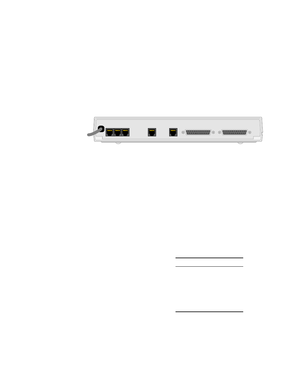
On the rear of the unit, there are seven port connections: LAN, SLIP, SUPV, DBU,
DDS, Port A and Port B as shown in Figure 2-1.
LAN
The unit has an 8-pin modular jack labeled LAN. It can be equipped with either an
internal Ethernet or Token Ring network interface card (NIC) for connection to a
local area network (LAN) without changing the rear panel. This port functions
only when the optional NIC is installed. If the NIC is not installed, use the SLIP
port connection (page 11).
Network management is performed through the LAN port as well as the SUPV
port (page 12) and the SLIP port (page 11). The unit incorporates the full TCP/IP
stack, supports in-bound Telnet, and has an embedded SNMP agent for trap
reporting or SNMP monitoring and management supporting the DDS specific and
TXPORT enterprise MIBs as listed in SNMP Agent on page 53.
Ethernet
The Ethernet interface complies with
standard twisted pair, 10BASE-T
requirements. Table 2-1 shows the
pinouts for the 8-pin modular
connection. Before connecting the
unit to the LAN, configure the LAN
interface using the SNMP Parameters
screen (page 23 for the front panel
interface or page 46 for the terminal
interface) of the unit firmware.
Figure 2-1 PRISM 41TDM (Rear View)
LAN
SLIP
SUPV
DDS
DBU
PORT A
PORT B
115VAC
50/60Hz
116ma
Table 2-1 Ethernet Pinout
Pin
Ethernet Interface
1
Data Out (+)
2
Data Out (-)
3
Data In (+)
4
Not Used
4
Not Used
6
Data In (-)