Token ring, Slip, Direct connection – Verilink PRISM 41TDM (34-00275.4) Product Manual User Manual
Page 19
Port Connections 11
Token Ring
The Token Ring interface (Type 3) is
designed to operate on both 4 and
16 Mbps networks and complies
with standard unshielded twisted
pair (UTP) requirements. Table 2-2
shows the pinout for the 8-pin
modular LAN connection.
Before connecting the unit to the
LAN, configure the LAN interface
using the SNMP Parameters screen
(page 23 for the front panel interface or page 46 for the terminal interface) of the
unit firmware. Connection to an IBM Type 1 cable requires a Verilink adapter kit
(9-1001-072-1). This kit includes an impedance matching adapter.
SLIP
The SLIP port is an 8-pin modular jack (electrically RS-232) DCE port configured
for 8 bits, no parity, and 1 stop bit. The bit rate defaults to 19200 bps but can be
changed through the terminal interface (see Management Ports on page 4 -18).
Refer to Customer Service on page iv for any cabling information. This port is
accessible through either a direct connection or a dial-up connection via an AT
command set compatible modem.
Network management is performed through the SLIP port as well as the LAN port
(page 10) and the SUPV port (page 12). The unit incorporates the full TCP/IP
stack, supports inbound Telnet, and has an embedded SNMP agent for trap
reporting or SNMP monitoring and management supporting the DDS specific and
TXPORT enterprise MIBs as listed in SNMP Agent on page 53.
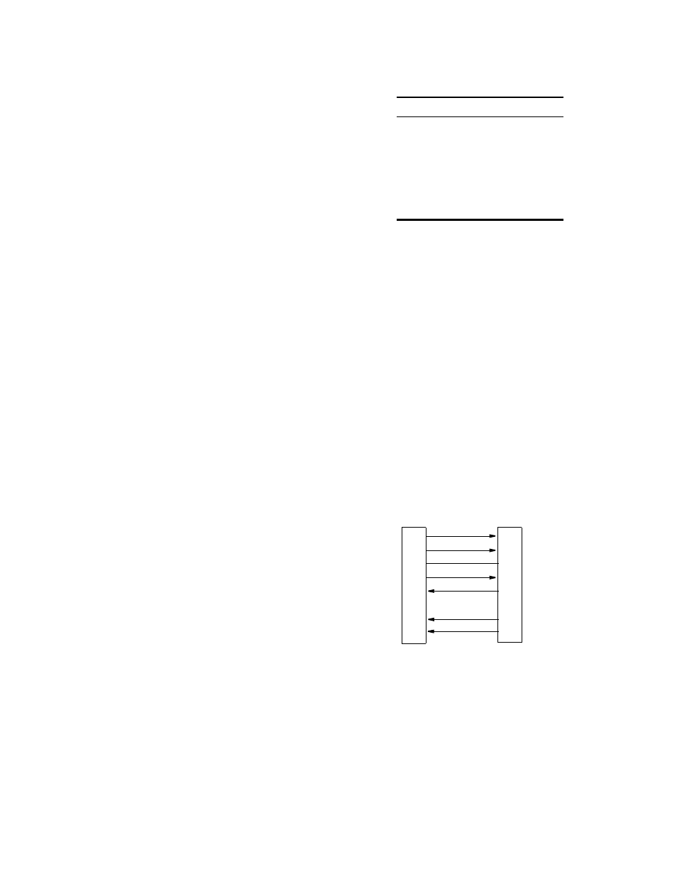
Direct Connection
The SLIP port connects to
a terminal server or router
that provides SLIP access
to the LAN. The TCP/IP
connection is always up in
this mode. An RS-232 to
terminal cable connection
(9-1001-073-2) must be
used.
Table 2-2 Token Ring Pinout Assignments
Pin
Token Ring Interface
1
Not Used
2
Not Used
3
Data Out (-)
4
Data In (+)
5
Data In (-)
6
Data Out (+)
DTR Out
1
RTS Out
2
Frame Gnd
3
Data Out
4
Data In
5
Signal Gnd
6
CTS In
7
DCD In
8
PC (DTE)
S
UPV
/S
LIP
Port
1 DCD
8
CTS
5
Frame Gnd
2
RXD
3
TXD
NC Signal Gnd
7
RTS
4
DTR
8-Pin Modular
DB-9
Figure 2-2 Terminal Connection Pinout Assignments